Tensioning or guide rail having an extruded sliding lining body

a technology of sliding lining body and tensioning rod, which is applied in the direction of belt/chain/gearing, mechanical equipment, belts, etc., can solve the problems of high production cost and total cost of manufacturing methods, and achieve the effect of improving the lateral fixing of sliding rods, ensuring reliable positioning during assembly and operation, and avoiding burdening production costs by increasing mounting efforts

Active Publication Date: 2017-03-28
IWIS MOTORSYSTEME GMBH & CO KG
View PDF31 Cites 7 Cited by
  • Summary
  • Abstract
  • Description
  • Claims
  • Application Information

AI Technical Summary

Benefits of technology

[0017]For laterally guiding the sliding body on the bearing surface and for securing it against lateral displacement, the sliding body may have at least one positioning web on its back facing away from the sliding surface, said positioning web being configured for engagement with the surface profile of an associated bearing surface of the supporting body. Such a positioning web, which projects e.g. from the back of the sliding body, improves the lateral fixing of the sliding body and guarantees reliable positioning during assembly and during operation, without burdening the production costs through increased mounting efforts. The positioning web may here be provided with an undercut, which encompasses the bearing surface o

Problems solved by technology

Since this manufacturing method is very work-intensive and the supporting body must be positioned precisely so that the

Method used


Image

  • Tensioning or guide rail having an extruded sliding lining body
  • Tensioning or guide rail having an extruded sliding lining body
  • Tensioning or guide rail having an extruded sliding lining body

Examples


first embodiment

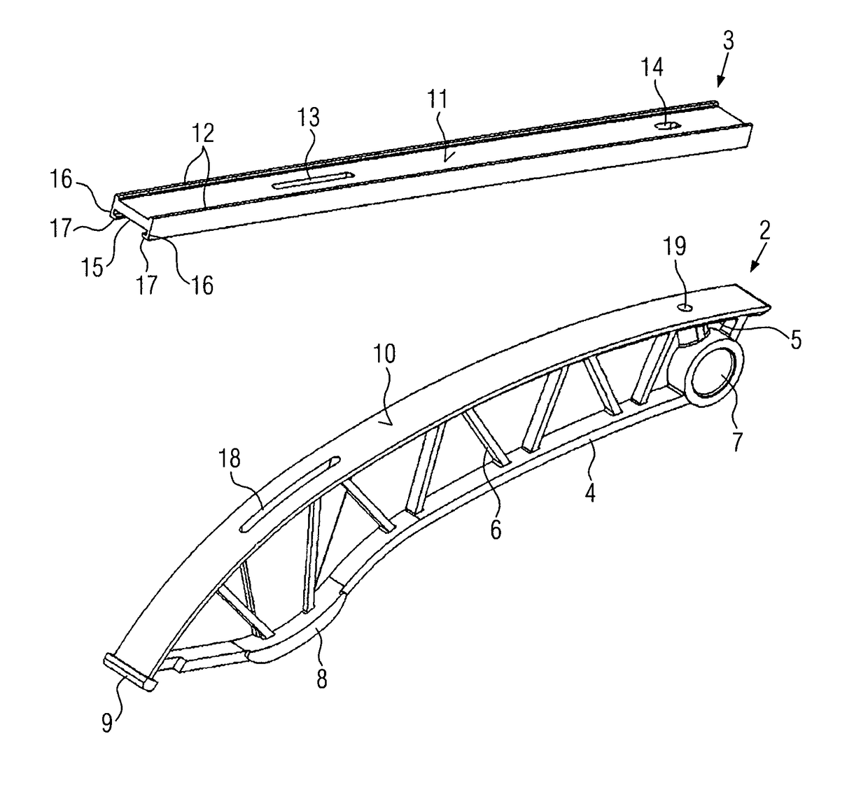
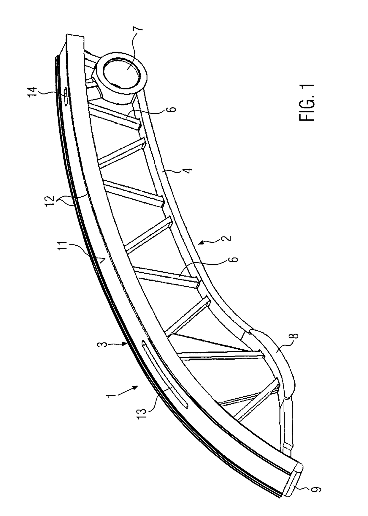
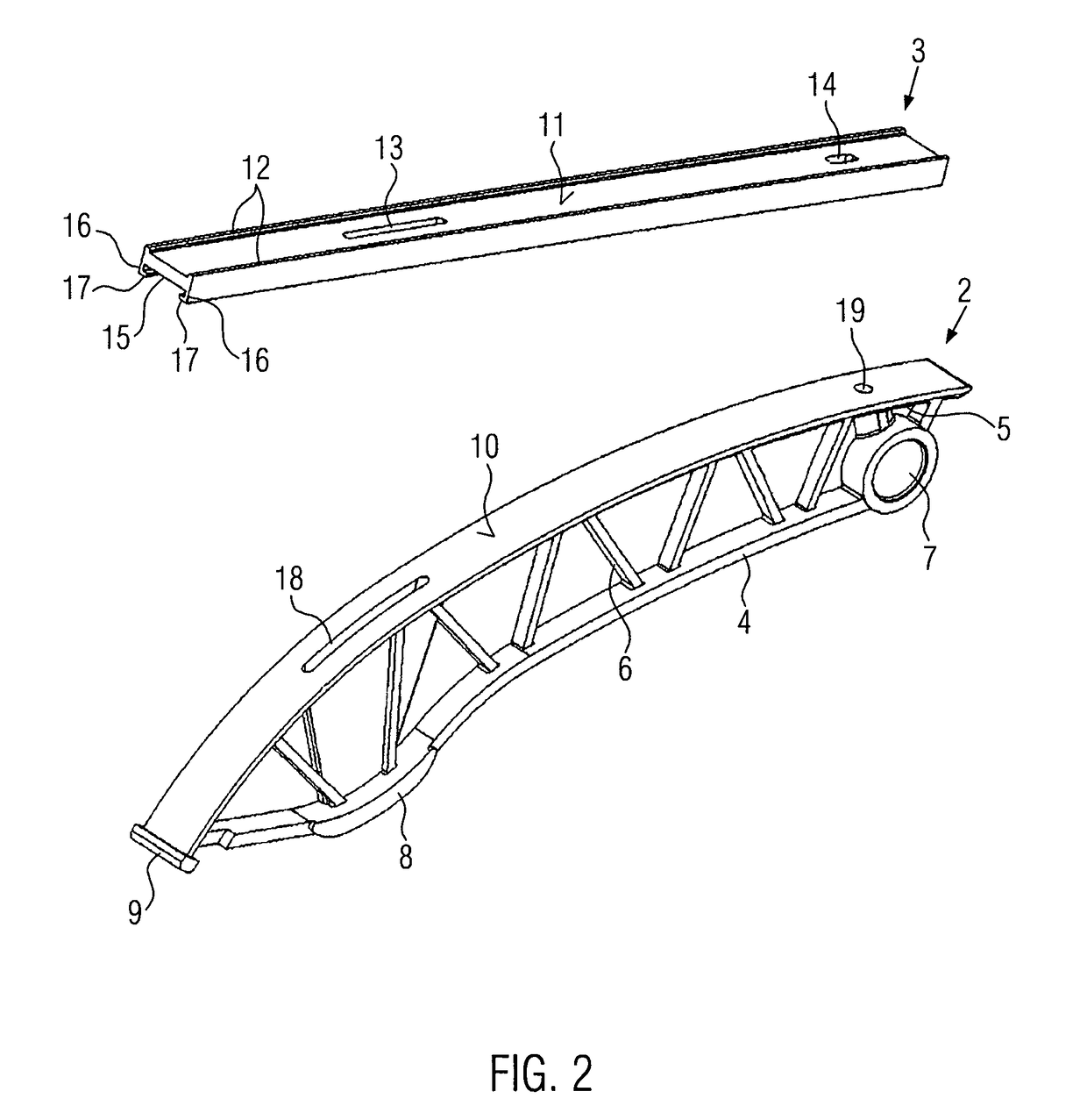
[0034]Another embodiment of a tensioning or guide rail 1 according to the present invention is shown in FIGS. 4 to 6. The features discussed hereinbelow are substantially the differing features of the different embodiments, whereas all those features of this further embodiment of a tensioning or guide rail 1 which are not described in detail are configured in accordance with the features that have been described in detail in the first embodiment in connection with FIGS. 1 to 3. As can be seen from the perspective side view of the tensioning or guide rail 1 in FIG. 4, said tensioning or guide rail 1 is again configured as a tensioning rail with a pivot bearing bushing 7 arranged on the bearing end and a press-on area 8 provided on the tensioning area. The supporting body 2 of this tensioning or guide rail 1 according to the present invention is again configured as a truss structure comprising a lower longitudinal support 4, an upper longitudinal support 5 and cross members 6. The sup...

second embodiment

[0035]The additional embodiment of a bipartite tensioning or guide rail 1 according to FIG. 4 is shown in FIG. 5 is a non-mounted condition. Here, it can be seen once more that the sliding body 3 is substantially straight in the non-mounted condition and adapts itself to the curved shape of the bearing surface 10 of the supporting body 2 only in the mounted condition. The pockets 21 arranged at the end faces of the bearing surface 10 are L-shaped and configured such that their width is narrower than that of the bearing surface 10, so that, in the assembled condition, the portions of the L-shape directed inwards, when seen in the direction of the bearing surface 10, are positioned over the sliding surface 11 of the sliding body 3. In this embodiment, the bearing surface 10 is simultaneously also the upper longitudinal support 5 of the supporting body 2 without projecting laterally therebeyond. In addition to the slot 18 and the opening 19 in the bearing surface 10, a ridge 22 is here...


PUM

PropertyMeasurementUnit
Tensionaaaaaaaaaa

Abstract

A tensioning or guide rail and a method of producing a tensioning or guide rail for an endless drive means are provided, in particular for a chain drive in an internal combustion engine, comprising a supporting body and a sliding body of plastic material arranged on the supporting body. The method comprises the steps of producing a sliding body profile strand and separating the individual sliding body from the sliding body profile strand. The sliding body of a tensioning or guide rail is a segment of such a sliding body profile strand, the plastic material being oriented in a longitudinal direction.

Description

CROSS-REFERENCE TO RELATED APPLICATIONS[0001]This application is a National Stage of International patent application PCT / EP2013 / 001682, filed on Jun. 7, 2013, which claims priority to foreign German patent application No. DE 102012014943.3, filed on Jul. 27, 2012, the disclosure of which are incorporated by reference in their entirety.FIELD OF THE INVENTION[0002]The present invention relates to a method of producing a tensioning or guide rail for an endless drive means, in particular for a chain drive in an internal combustion engine, comprising a supporting body and a sliding body arranged on the supporting body. In addition, the present invention relates to such a tensioning or guide rail in which the sliding body made of plastic material has a sliding surface for contacting the endless drive means.BACKGROUND[0003]In technology, a large number of tensioning or guide rails is used for internal combustion engines, in particular for timing drives. In this field of use, high demands ...

Claims


Application Information

Patent Timeline
IPC IPC(8): F16H7/08F16H7/18
CPCF16H7/18F16H7/08F16H2007/0872F16H2007/0893F16H2007/185Y10T29/49826
Inventor GEIBEL, HENNINGPERISSINOTTO, RENZO
Owner IWIS MOTORSYSTEME GMBH & CO KG
Why Eureka
Try Eureka