Magnetic resonance apparatus

a magnetic resonance and apparatus technology, applied in the direction of using reradiation, magnetic variable regulation, instruments, etc., can solve the problems of difficult sealing of the acoustic bridge and/or sound bridge of the housing casing on the front face and/or the rear face of the magnetic resonance apparatus, and the noise is loud,

Inactive Publication Date: 2017-03-28
SIEMENS HEALTHCARE GMBH
View PDF25 Cites 0 Cited by
  • Summary
  • Abstract
  • Description
  • Claims
  • Application Information

AI Technical Summary

Benefits of technology

[0008]The present embodiments may obviate one or more of the drawbacks or limitations in the related art. For example, in some embodiments, a housing casing unit is provided that reduces and / or prevents acoustic bridges and / or sound bridges between the individual casing parts.
[0011]In some embodiments, acoustic bridges and / or sound bridges within the housing casing unit may be reduced. In some embodiments, acoustic bridges and / or sound bridges may be reduced and / or closed at boundary regions between two adjoining components and / or structural units of the housing casing unit, thereby reducing sound emission and / or the emission of sound waves into a region enclosing the magnet unit and the housing casing unit. During operation of the magnetic resonance apparatus, a reduction in a sound pressure level of 5 dB and, in some embodiments, 10 dB may be achieved after the barrier or membrane unit along a propagation direction of the sound waves (e.g., air-borne sound waves). Thus, a magnetic resonance apparatus with less noise and / or sound may be provided, thereby reducing sound exposure for the patient during a magnetic resonance examination. In addition, the membrane unit may protect the magnet unit and / or additional components (e.g., electronic components) from fluids (e.g., body fluids from a patient and / or cleaning fluids).
[0014]At least one membrane unit is disposed along a transmission path and / or a propagation path of the sound waves emitted from the magnet unit between the magnet unit and at least one casing part. The membrane unit may be disposed in such a way that the membrane unit is well protected from unwanted damage (e.g., when a patient support apparatus is introduced into a patient-receiving region of the magnetic resonance apparatus enclosed in a cylindrical manner by the high-frequency antenna unit). In some embodiments, the membrane unit may be provided with an air-borne sound wave-damping function, thereby providing a low-cost membrane unit. The at least one membrane unit may also form a double-shell casing together with the at least one casing part. The at least one casing part may be optimized for impermeability of structure-borne sound waves. The at least one membrane unit and the at least one casing part may be configured separately from one another.
[0019]In some embodiments, the membrane unit at least partially has the form of a truncated cone. The truncated cone configuration allows the membrane unit to cover at least one boundary region completely and without gaps in a circumferential direction. Differing distances between the boundary surfaces of a boundary region along the circumferential direction (e.g., due to manufacturing tolerances and / or assembly tolerances) may be shielded by the membrane unit for air-borne sound waves. The truncated cone form corresponds to a hose-type configuration of the membrane unit with different opening surfaces on the end regions.
[0023]Alternatively, the fastening element may be disposed on a face of the casing part of the front casing unit and / or the rear casing unit facing the magnet unit. The fastening element may be actuated, for example, from a face of the casing part of the front casing unit and / or the rear casing unit facing away from the magnet unit. The at least one fastening element may thus be protected from unwanted damage and a space-saving arrangement and a compact housing casing may be achieved.
[0024]In some embodiments, the fastening unit has at least one fastening element that is formed by a form-fit element. A structurally simple and releasable fastening and / or connection of the membrane unit to the high-frequency antenna unit and / or a casing part (e.g., of the front casing unit and / or the rear casing unit) may be achieved. The form-fit element may be formed by a tensioning element and / or a clamping element. Arrangement on and / or fastening to an additional part (e.g., to the high-frequency antenna unit and / or the casing part) may be achieved such that there are no acoustic bridges, sound wave bridges, and / or sound wave permeability (e.g., of air-borne sound waves).

Problems solved by technology

When magnetic resonance apparatuses operate, an interaction between a gradient coil unit and a main magnet of a magnet unit may result in loud noises (e.g., knocking).
However, consideration of additional factors makes it more difficult to reduce and / or seal the acoustic bridges and / or sound bridges of the housing casing on the front face and / or on the rear face of the magnetic resonance apparatus.
However, these solutions have a disadvantage in that a harder seal is more impermeable to air-borne sound and transmits structure-borne sound to a greater degree.
The form of the tapering insertion unit results in a trumpet-like transmission of structure-borne sound to the tapering insertion unit, thereby causing undesirable sound exposure for the patient.

Method used


Image

  • Magnetic resonance apparatus
  • Magnetic resonance apparatus
  • Magnetic resonance apparatus

Examples


Embodiment Construction

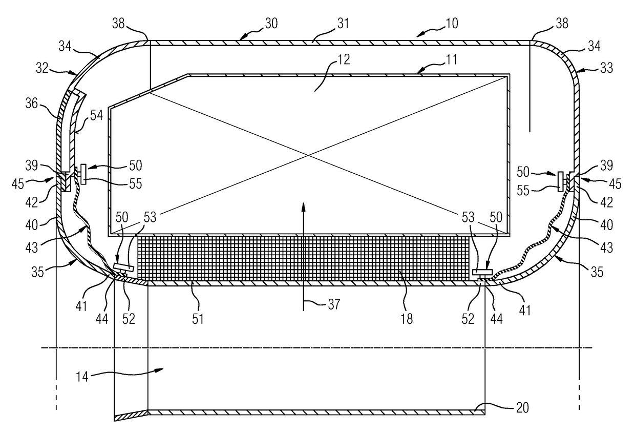
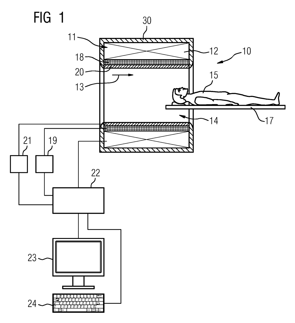
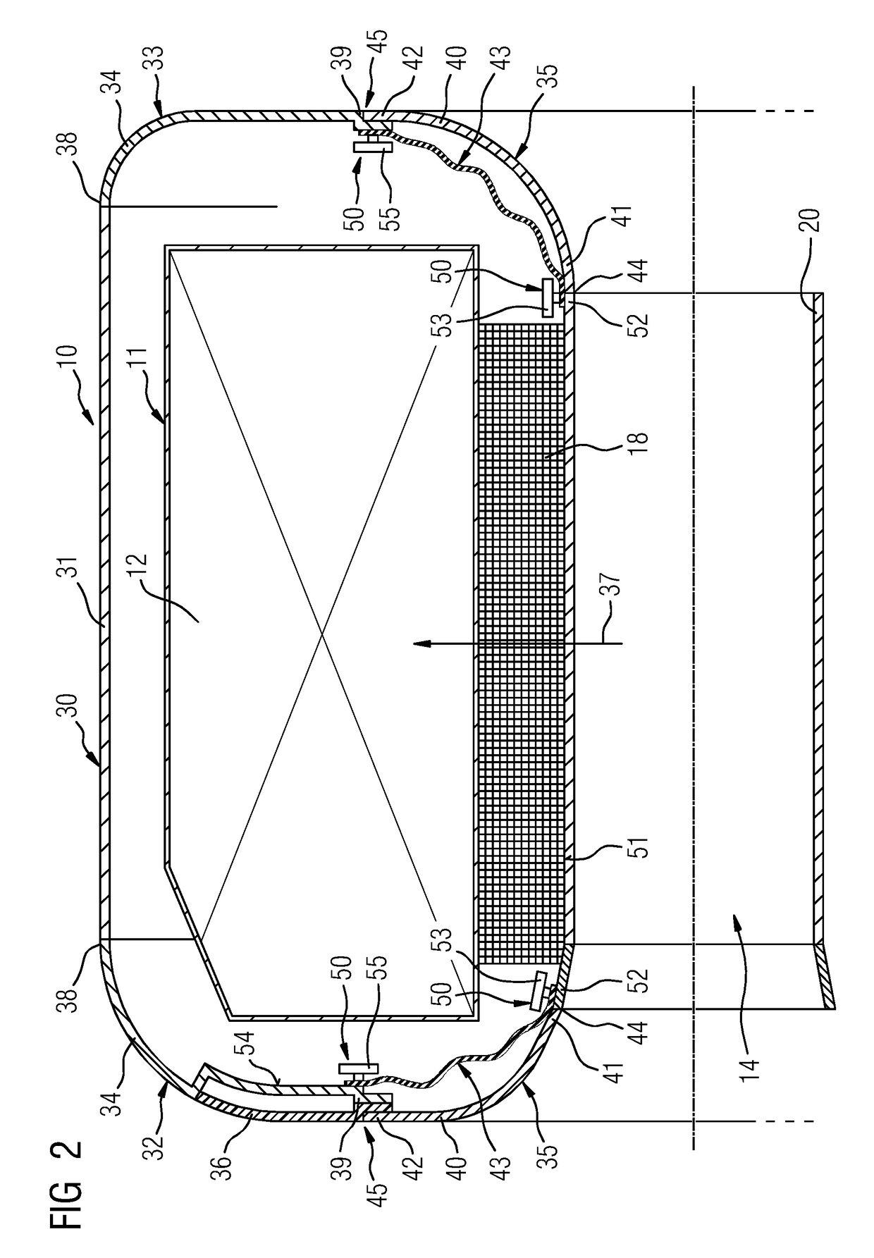
[0029]FIG. 1 shows a schematic diagram of a magnetic resonance apparatus 10. The magnetic resonance apparatus 10 includes a magnet unit 11 with a main magnet 12 configured for generating a powerful and constant main magnetic field 13. The magnetic resonance apparatus 10 has a cylindrical patient-receiving region 14 configured for receiving a patient 15. The patient-receiving region 14 is enclosed cylindrically in a circumferential direction by a housing casing unit 30 of the magnetic resonance apparatus 10 enclosing the magnet unit 11. The patient 15 may be moved into the patient-receiving region 14 by a patient support apparatus 17 of the magnetic resonance apparatus 10. The patient support apparatus 17 is movably disposed within the patient-receiving region 14.

[0030]The magnet unit 11 includes a gradient coil unit 18 configured for generating magnetic field gradients that is used for spatial encoding during imaging. The gradient coil unit 18 is controlled by a gradient control uni...


PUM


Abstract

A magnetic resonance apparatus includes a magnet unit that contains a high-frequency antenna unit, and a housing casing unit enclosing the magnet unit. The housing casing unit includes a side casing unit, a front casing unit, and a rear casing unit. The side casing unit, the front casing unit, and / or the rear casing unit includes at least one casing part. At least one boundary region of the housing casing unit is disposed between the different casing parts. The housing casing unit includes at least one membrane unit that contains a barrier for the propagation and / or transmission of sound waves and that covers at least one boundary region between two casing parts.

Description

RELATED APPLICATIONS[0001]This application claims the benefit of German Patent Application No. DE 102013202163.1, filed Feb. 11, 2013, the entire contents of which are hereby incorporated herein by reference.TECHNICAL FIELD[0002]The present teachings relate generally to a magnetic resonance apparatus that includes a magnet unit containing a high-frequency antenna unit, and a housing casing unit that encloses the magnet unit and includes a side casing unit, a front casing unit and a rear casing unit. The side casing unit, the front casing unit, and / or the rear casing unit each includes at least one casing part. At least one boundary region of the housing casing unit is disposed between the different casing parts.BACKGROUND[0003]When magnetic resonance apparatuses operate, an interaction between a gradient coil unit and a main magnet of a magnet unit may result in loud noises (e.g., knocking). Noise and / or sound waves escape and / or are emitted in a region enclosed by the magnetic reso...

Claims


Application Information

Patent Timeline
Patent Type & Authority Patents(United States)
IPC IPC(8): G01V3/00G01R33/34G01R33/385G01R33/28
CPCG01R33/34G01R33/3854G01R33/28
Inventor MACIEJEWSKI, BERNDSTEIN, ANNETTE
Owner SIEMENS HEALTHCARE GMBH
Why Eureka
Try Eureka