Radiographic device

a technology of radiographic devices and figs, applied in the direction of radiation generation arrangements, medical science, diagnostics, etc., can solve problems such as the deviation of figs at the joint of images, and achieve the effect of reducing excessive load

Inactive Publication Date: 2017-04-04
SHIMADZU CORP
View PDF7 Cites 8 Cited by
  • Summary
  • Abstract
  • Description
  • Claims
  • Application Information

AI Technical Summary

Benefits of technology

[0030]With the radiographic apparatus of the present invention, successive imaging is performable while a timing to activate the radiation source in the rest state is acquired appropriately. That is, with the configuration of the present invention, the difference time is calculated by subtracting the time width of the activation time period from the time width of the non-detectable time period. Then, the time after the difference time has elapsed from the radiation emission time is determined as a timing to activate the radiation source. Here, the time width of the non-detectable time period is a time width from the detection of radiation to subsequent performable detection of radiation by the detector. The time width of the activation time period is a time width from beginning to completion of activation of the radiation source. This allows rapid successive imaging while the activation of the radiation source and preparation of the detector are performed simultaneously, allowing suppression of excessive load to the radiation source and a prolonged life of the radiation source.

Problems solved by technology

That is because a longer time period between the adjacent imaging causes movement of the subject during the imaging, leading to a deviation of FIGs at a joint of the images.

Method used


Image

  • Radiographic device
  • Radiographic device
  • Radiographic device

Examples


embodiment 1

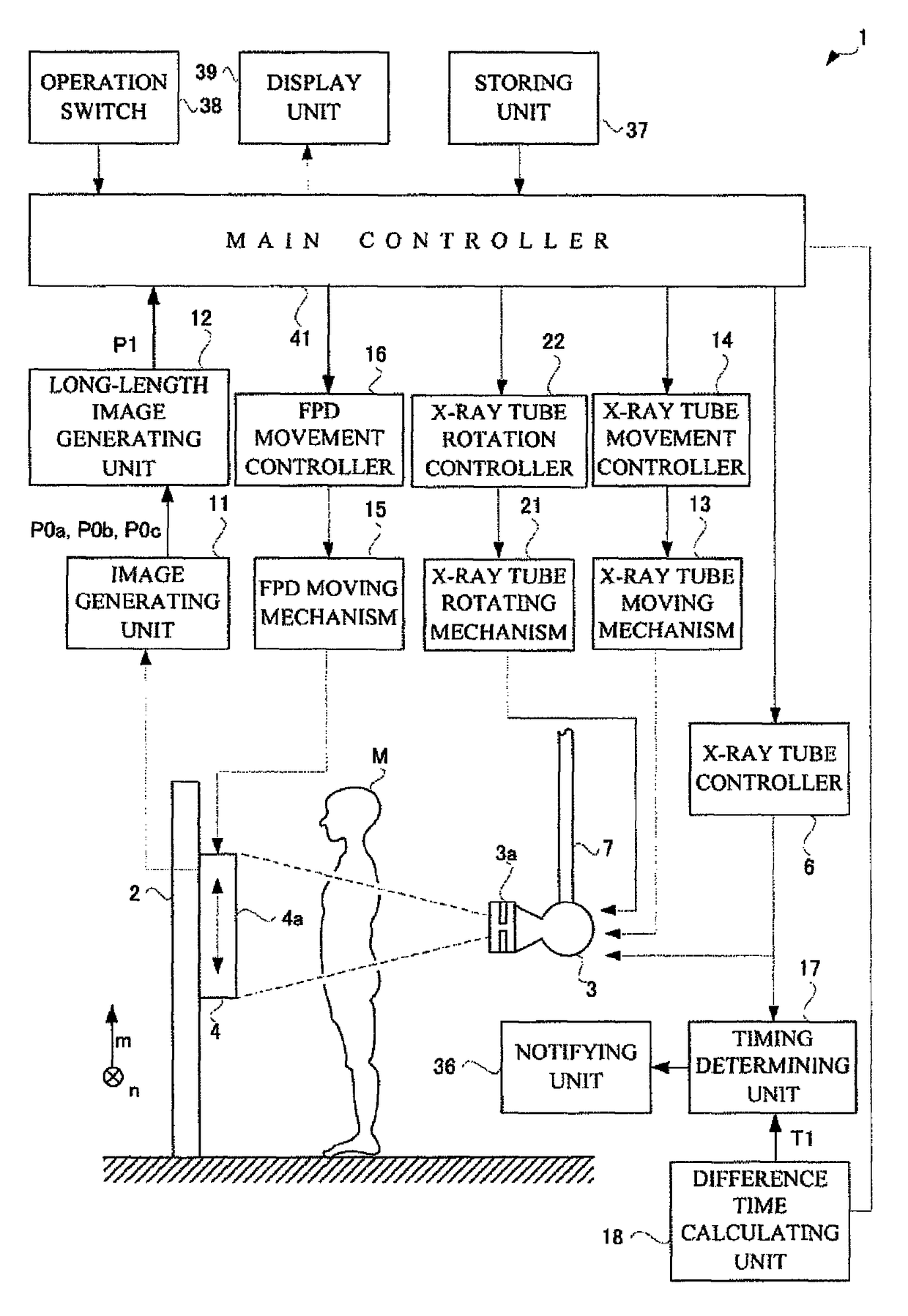
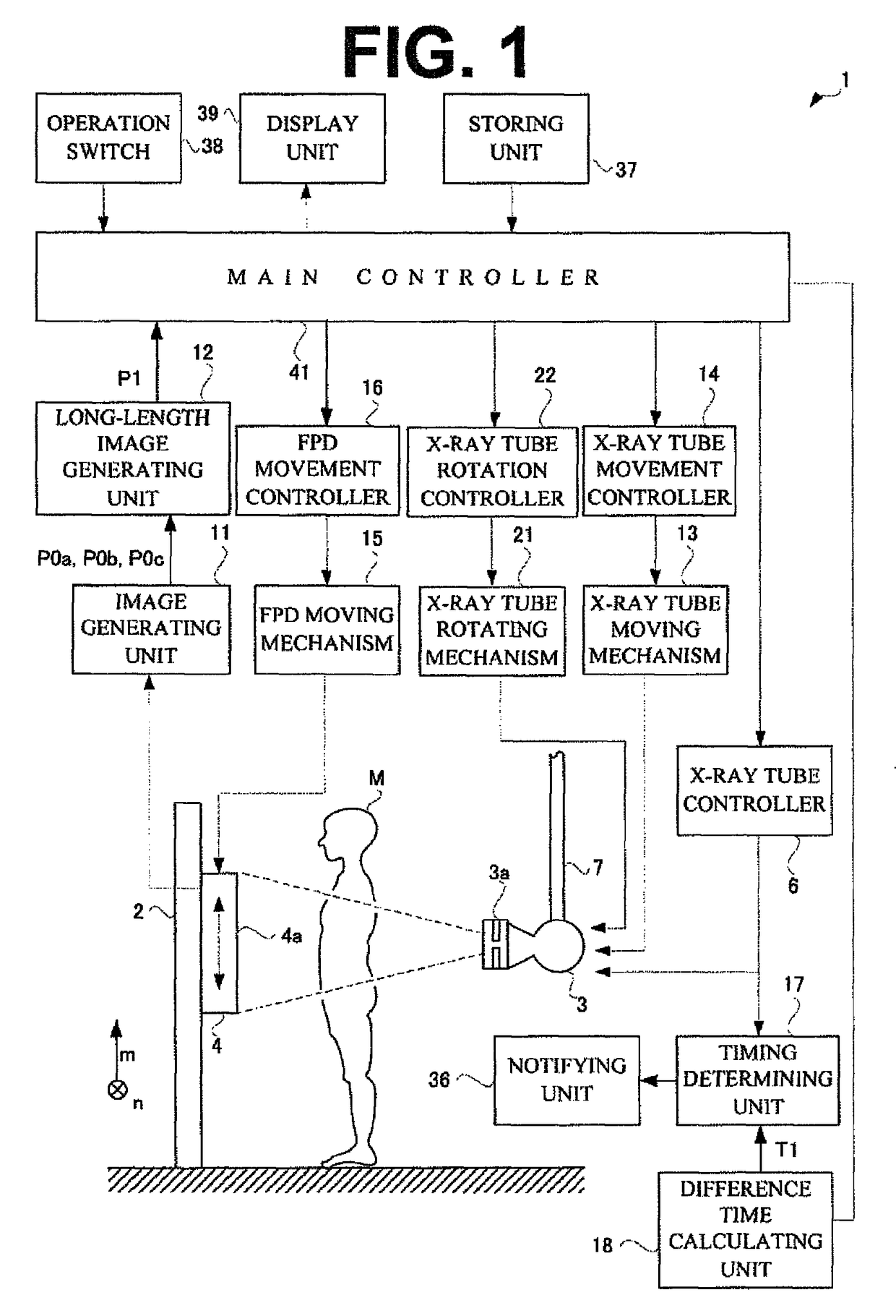
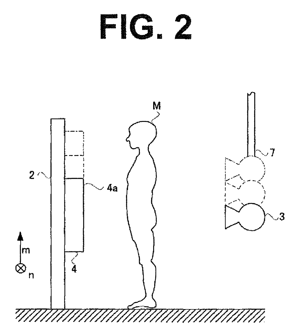
[0046]The following firstly describes an X-ray apparatus 1 according to Embodiment 1. Here, the configuration of Embodiment 1 adopts an improvement over a conventional manual mode. The X-ray apparatus 1 images a standing subject M. As illustrated in FIG. 1, the X-ray apparatus 1 includes a strut 2 extending vertically from the floor, an X-ray tube 3 emitting X-rays, an FPD 4 supported on the strut 2, and a suspending holder 7 extending vertically and held on the ceiling. The suspending holder 7 suspendingly holds the X-ray tube 3. The X-ray tube 3 corresponds to the radiation source in the present invention. The FPD 4 corresponds to the detecting means in the present invention.

[0047]A collimator 3a is provided for restricting an area of X-rays emitted from the X-ray tube 3. An operator adjusts a leaf of the collimator 3a, and correspondingly an emission area of X-rays becomes larger or smaller.

[0048]The FPD 4 is slidable vertically relative to the strut 2. The suspending holder 7 is...

embodiment 2

[0085]The following describes an X-ray apparatus 1 according to Embodiment 2. The X-ray apparatus 1 according to Embodiment 2 is similar to Embodiment 1 in its configuration. Accordingly, description about the configuration of Embodiment 2 common to that of Embodiment 1 is to be omitted. The configuration of Embodiment 2 is improvement of the conventional automatic mode.

[0086]Embodiment 2 differs from Embodiment 1 in that long-length radiography for the second and subsequent times is performed automatically. That is, the X-ray apparatus 1 in Embodiment 2 allows successive radiography of a plurality of images by merely one-time instruction to activate the X-ray tube 3 and one-time instruction to emit X-rays by an operator.

[0087]FIGS. 9(A), 9(B) illustrate a timing chart illustrating performance of long-length radiography with the X-ray apparatus 1 of Embodiment 2. An upper sequence 9(A) of the drawing indicates a state of the X-ray tube 3, and a lower sequence (9B) indicates a state ...


PUM


Abstract

According to this radiography device, by taking images in rapid succession while appropriately obtaining the timing for which an X-ray tube in a rest state should be activated, rapid successive imaging and protection of a radioactive source can both be achieved. That is, in the configuration of the present invention, a time difference is calculated, obtained by subtracting a temporal width of an activation period from a temporal width of an undetectable period, and the time after the time difference has elapsed from the time at which an X-ray is irradiated is determined as the timing for activating the X-ray tube. The temporal width of an undetectable period is the temporal width between the time at which an FPD detects an X-ray once and the time at which the following X-ray can be detected, and the temporal width of an activation period is the temporal width between the start of activation of the X-ray tube to the completion of activation. Thus, while simultaneously activating the X-ray tube and preparing the detector, images can be taken in rapid succession without excessive burden on the X-ray tube and the life of the X-ray tube can be extended.

Description

CROSS REFERENCE TO RELATED APPLICATIONS[0001]This application is the U.S. National Phase under 35 U.S.C. §371, of International Application No. PCT / JP2013 / 000013, filed on Jan. 8, 2013, the disclosures of which is incorporated fully by reference.FIGURE SELECTED FOR PUBLICATION[0002]FIG. 1BACKGROUND OF THE INVENTION[0003]Technical Field[0004]The present invention relates to a radiographic apparatus that emits radiation to a subject to take a fluoroscopic image. More particularly, the present invention is directed to a radiographic apparatus that allows plural-time imaging successively.[0005]Background Art[0006]A medical institution is equipped with a radiographic apparatus that emits radiation to image a subject M. See, for example, Patent Literature 1. Such a radiographic apparatus includes a radiation source 53 emitting radiation, and an FPD 54 detecting radiation, as illustrated in FIG. 13. The subject M stands between the radiation source 53 and the FPD 54.[0007]The radiographic ...

Claims


Application Information

Patent Timeline
Patent Type & Authority Patents(United States)
IPC IPC(8): H05G1/56A61B6/00
CPCA61B6/486A61B6/40A61B6/5241A61B6/542A61B6/461A61B6/54
Inventor OKUNO, TOMOHARUFUJII, HIDEKI
Owner SHIMADZU CORP
Why Eureka
Try Eureka