Rotating needle driver and apparatuses and methods related thereto

a technology of rotating needles and needles, which is applied in the field of rotating needle drivers, can solve the problems of inability to achieve satisfactory compromises solely based on errors in aiming in-situ targets, and achieve the effects of reducing insertion forces, reducing static friction, and reducing forces

Active Publication Date: 2017-04-04
THE JOHN HOPKINS UNIV SCHOOL OF MEDICINE
View PDF29 Cites 7 Cited by
  • Summary
  • Abstract
  • Description
  • Claims
  • Application Information

AI Technical Summary

Benefits of technology

[0014]This combined rotating and translating of the medical instrument causes the medical instrument to spiraling as it pierces and traverses the tissue to the target area instead of deflecting on a side as with conventional drivers. In this way, the inserted end of the medical instrument ends up closer to the target as compared to conventional drivers.
[0015]Such spiraling motion also should break the static friction between the tissue and the target reducing forces, as well as possibly reducing insertion forces by the “drilling” effect of the spiral motion. It also is expected that such rotating and translating movement of the medical device collectively reduces deformations by reducing interaction forces, as strains are directly related to stress.
[0023]The translation and rotational mechanism of the present invention is particularly advantageous as it yields a compact design as compared to conventional drivers and so that the medical instrument driver of the present invention is less tall than the medical device, e.g., needle. This compactness is particular advantageous as it allows for fitting the driver of the present invention into the compact space of the imagers. As indicated above, needle insertion is a translation and conventional translation stages typically are larger than their stroke. The translational structure of the present invention on the other hand embodies an optimized crank hinged slider rod mechanism that renders near translational motion with a compact design. Also, linear motion with conventional drivers is implemented using a translational joint. In the present invention, such linear motion or near linear motion is accomplished using a combination of rotary joints.

Problems solved by technology

Commonly, the highest causes of errors in aiming an in-situ target with the point of the needle are deflections: soft tissue deflections and needle bending.
Apparently, there is no satisfactory compromise solely based on the gauge of the needle, and in fact most of the time needles are selected based on other clinical or availability criteria.

Method used


Image

  • Rotating needle driver and apparatuses and methods related thereto
  • Rotating needle driver and apparatuses and methods related thereto
  • Rotating needle driver and apparatuses and methods related thereto

Examples


example 1

[0120]A study was undertaken to evaluate two features of a new rotating needle driver in a domestic swine model: (1) a quick release safety mechanism and (2) the impact of spinning the needle on the force profile.

Materials and Methods

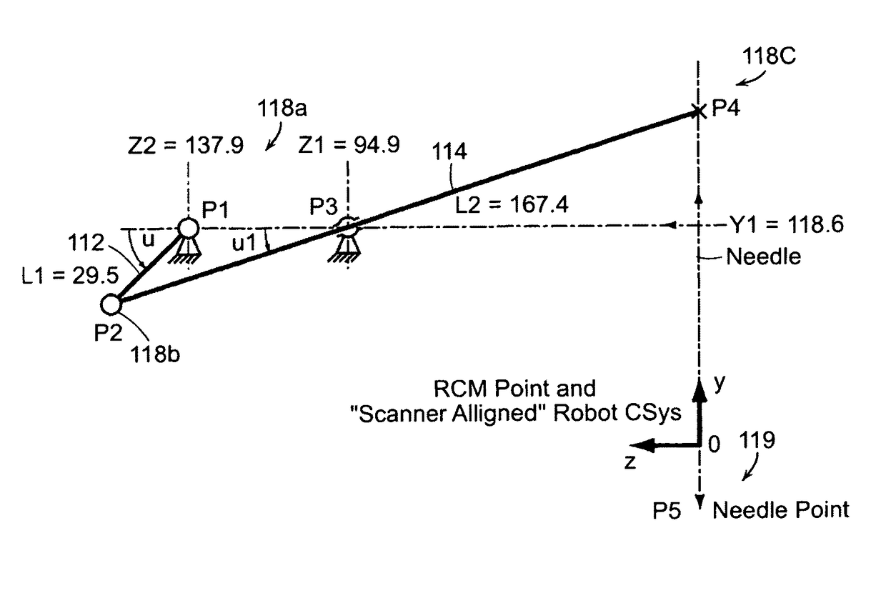
[0121]The robotic system used in these experiments is an updated version of the “AcuBot” system built by the Urology Robotics Laboratory at Johns Hopkins Medical Institutions. The original AcuBot included the “PAKY” (Percutaneous Access of the KidneY) needle driver, the “RCM” (Remote Center of Motion) orientation module, and joystick control. A three degree of freedom Cartesian stage, passive positioning S-arm, and “bridge frame” enable the system to achieve a compact and flexible design for interventions at multiple points along the body.

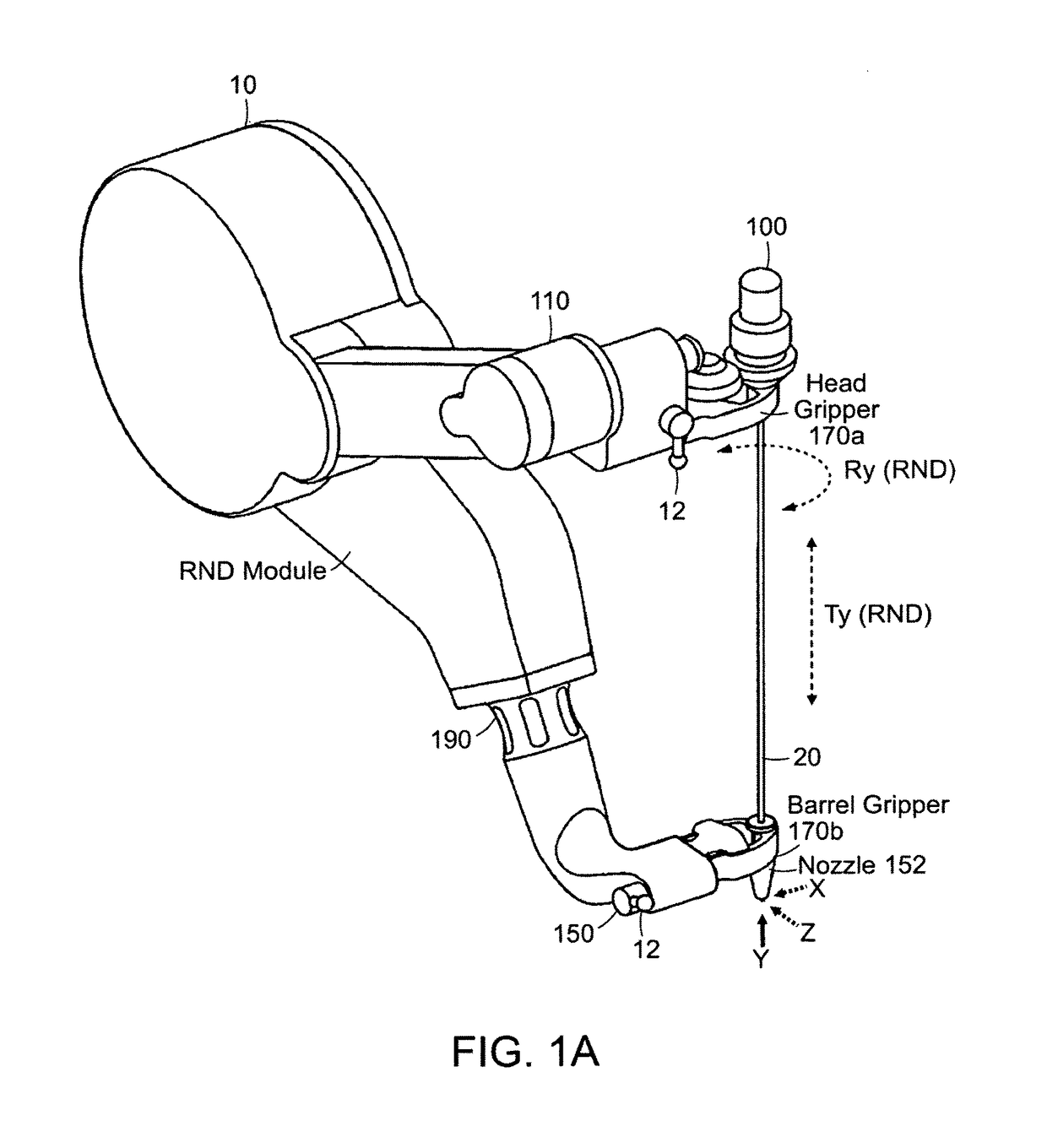
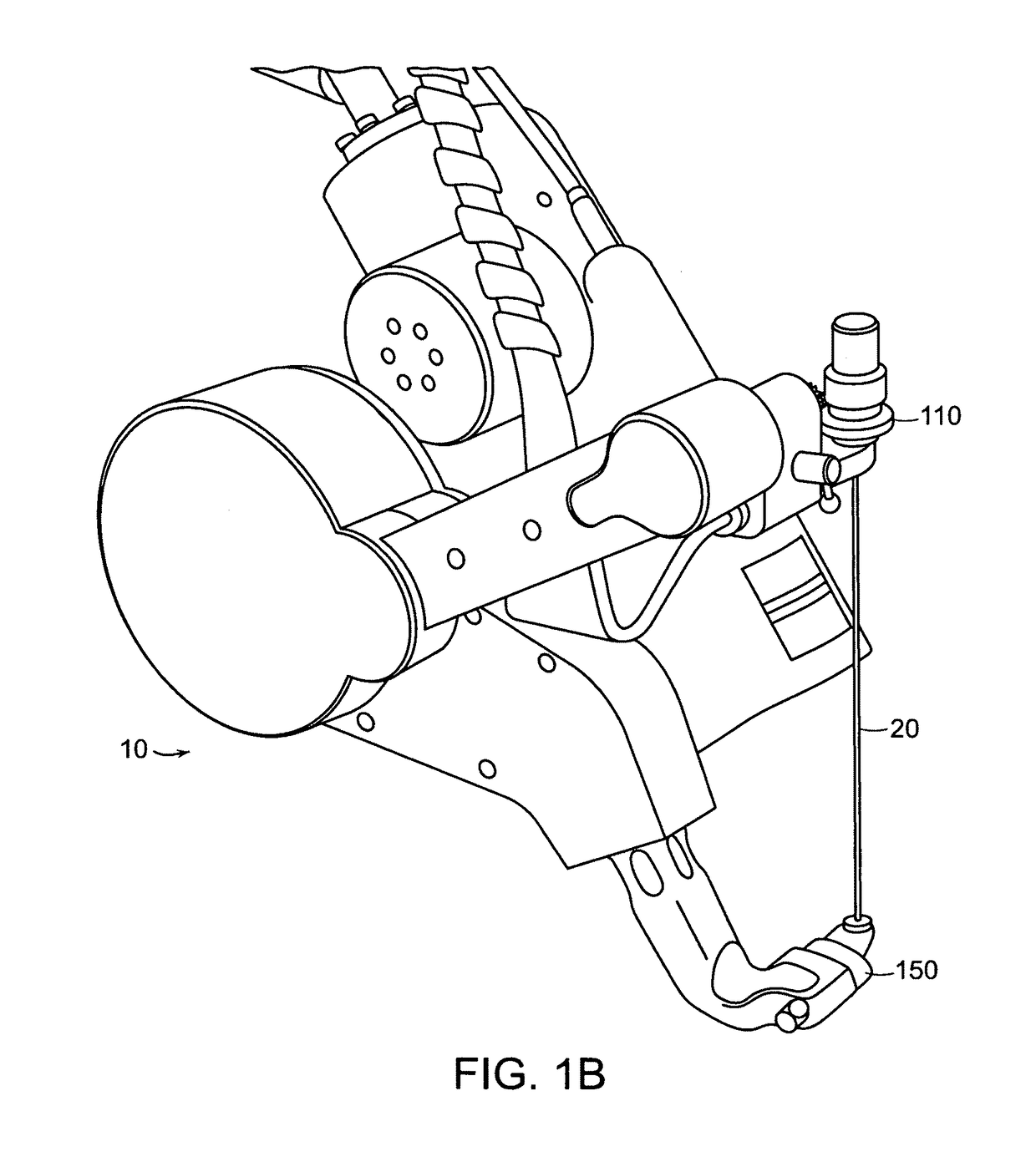
[0122]A compact medical instrument driver (RND) was provided that holds the needle from two points for enhanced support and accurate insertions. This design prevents buckling of long thin needles. Moreover, it is capab...


PUM


Abstract

Featured is a medical instrument driver, a robotic apparatus embodying such a medical instrument driver and methods related thereto for inserting a medical instrument into tissue of a mammal (e.g., human). Such medical instruments include medical needles, biopsy needles, trocars, cutters and introducers. Such a medical instrument driver according to the present invention is configured and arranged so that medical instrument is rotated as it is being moved longitudinally for insertion into the tissue such that the medical instrument is spiraling as it pierces and traverses the tissue to the target area.

Description

[0001]This application claims the benefit of U.S. Provisional Application Ser. No. 61 / 111,543 filed Nov. 5, 2008, the teachings of which are incorporated herein by reference.STATEMENT REGARDING FEDERALLY-SPONSORED RESEARCH[0002]The present invention was supported by a grant from the National Institute of Health, grant number CA094274. The U.S. Government may have certain rights to the present invention.FIELD OF INVENTION[0003]The present invention generally relates to apparatuses, devices and methods for the insertion of medical needles and other medical instruments into tissue and more specifically to apparatuses, devices and methods for the insertion of medical instruments such as medical needles, biopsy needles, trocars, cutters and introducers into tissue while rotating the medical instrument as it is being moved longitudinally for insertion into the tissue.BACKGROUND OF THE INVENTION[0004]Image-guided robots are manipulators that operate based on medical images. These are moder...

Claims


Application Information

Patent Timeline
Patent Type & Authority Patents(United States)
IPC IPC(8): A61F11/00A61B34/00A61B34/30A61B90/11A61B10/02
CPCA61B34/70A61B34/30A61B90/11A61B10/0233
Inventor STOIANOVICI, DANPETRISOR, DORUMAZILU, DUMITRUPATRICIU, ALEXANDRUGRUIONU, LUCIAN GHEORGHE
Owner THE JOHN HOPKINS UNIV SCHOOL OF MEDICINE
Why Eureka
Try Eureka