
Dead time reducer for piston actuator

a piston actuator and reducer technology, applied in the direction of machine/engine, pump control, non-positive displacement fluid engine, etc., can solve the problems of compressor damage, delay (e.g., dead time) associated with pulsation and shock to the entire compressor and pipe arrangement, and the effect of reducing the size of the piston actuator

Active Publication Date: 2017-04-04
CONTROL COMPONENTS INC
View PDF20 Cites 0 Cited by
  • Summary
  • Abstract
  • Description
  • Claims
  • Application Information

AI Technical Summary

Benefits of technology

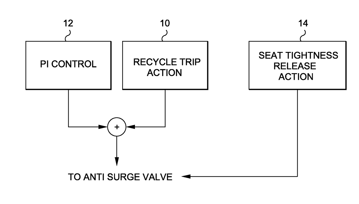
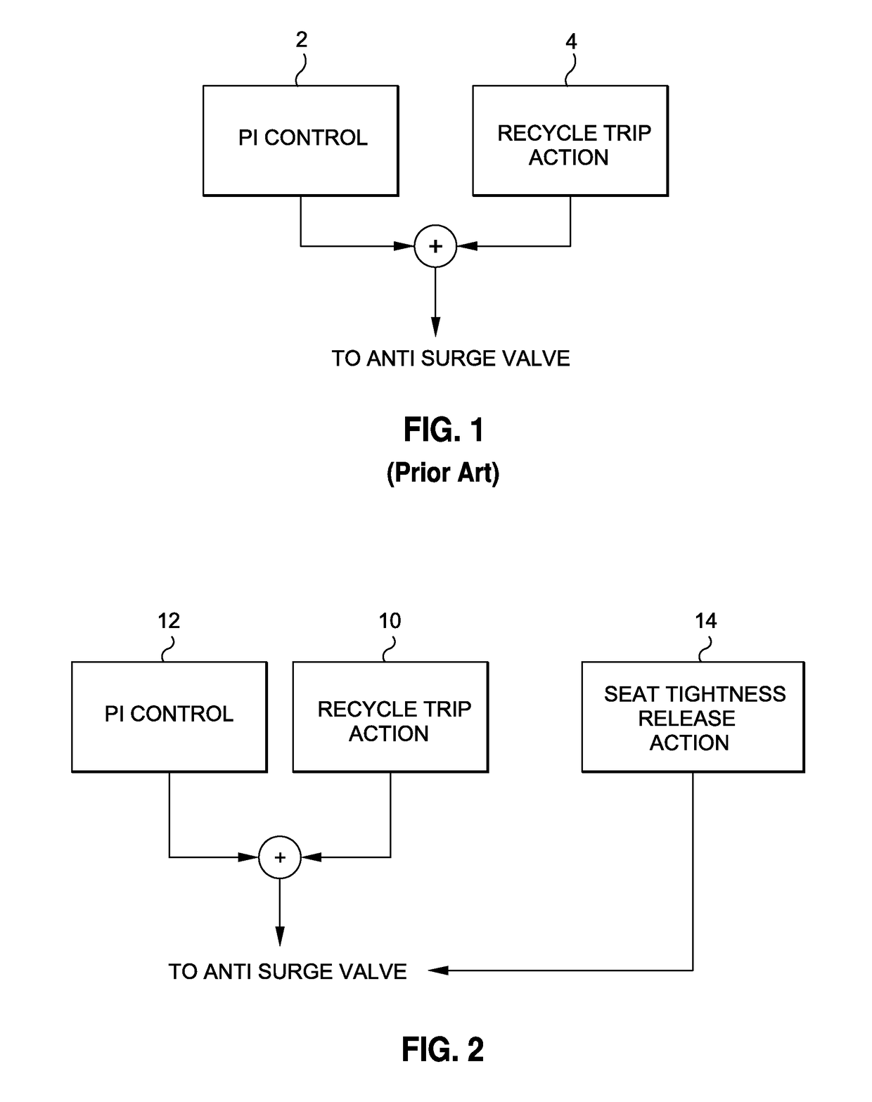
[0029]From this situation, with the actuator ready to move, the valve will react more promptly to an opening signal (fully open by SOV or control by signal) and the dead time on the seat will become very low, and thus, the total time to complete the stroke or control step is shorter.

Problems solved by technology

The occurrence of cyclical surge events may cause pulsation and shock to the entire compressor and pipe arrangement.
If left uncontrolled, damage to the compressor could result.
A common deficiency associated with conventional antisurge control systems is that there is a delay (e.g., dead time) associated with moving the valve from its closed position to its incipient open position.
This delay is typically due to the additional force given by the actuator, necessary to guarantee tightness between the plug and the seat of the valve.
In that case, the control of the operating point may not be accurate.
The higher the distance between the SCL and SLL, the higher the safety of compressor operation, but at a price of greater inefficiencies, since a part of the compressor map showing good efficiency cannot be used.

Method used


Image

  • Dead time reducer for piston actuator
  • Dead time reducer for piston actuator
  • Dead time reducer for piston actuator

Examples


Embodiment Construction

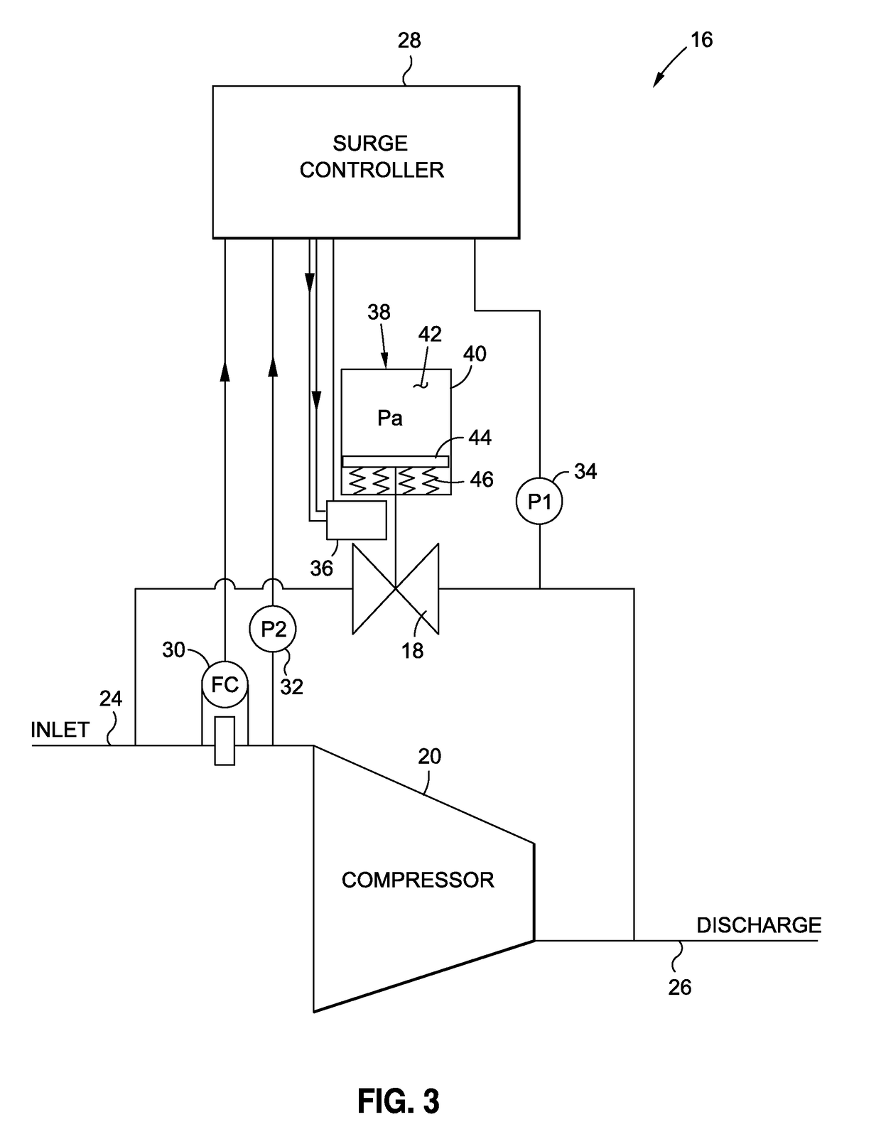
[0045]The detailed description set forth below in connection with the appended drawings is intended as a description of certain embodiments of control system for an anti-surge valve and is not intended to represent the only forms that may be developed or utilized. The description sets forth the various functions in connection with the illustrated embodiments, but it is to be understood, however, that the same or equivalent functions may be accomplished by different embodiments that are also intended to be encompassed within the scope of the present disclosure. It is further understood that the use of relational terms such as first and second, and the like are used solely to distinguish one entity from another without necessarily requiring or implying any actual such relationship or order between such entities.

[0046]As will be described in detail below, various aspects of the present invention relate to a control system for an antisurge valve that is capable of anticipating the recyc...


PUM


Abstract

An anti-surge system capable of anticipating a surge event in a compressor for readying the actuator to quickly actuate the anti-surge valve from the closed position to the open position. The control system includes a compressor surge controller configured to transmit a signal to the valve positioner when the operating point of the valve is approaching the surge control line. The compressor surge controller may monitor an operating margin equal to the difference between the operating point and the surge control line, and when the operating margin falls below a prescribed threshold, the compressor surge controller may send a signal to the positioner. In turn, the positioner may vent some pressure from the actuator. In this way, the dead time of the anti-surge valve on the valve seat is minimized and the valve will react more promptly to an opening signal.

Description

CROSS-REFERENCE TO RELATED APPLICATIONS[0001]Not ApplicableSTATEMENT RE: FEDERALLY SPONSORED RESEARCH / DEVELOPMENT[0002]Not ApplicableBACKGROUND OF THE INVENTION[0003]1. Field of the Invention[0004]The present invention relates generally to control systems for a compressor, and more particularly, to an anti-surge valve configured to anticipate surge conditions for purposes of reducing valve dead time on a valve seat when action is required by a compressor controller.[0005]2. Description of the Related Art[0006]Compressors are frequently employed in many industrial applications. One of the primary concerns associated with the operation of a compressor is compressor surge, which typically occurs in a centrifugal or axial compressor when the inlet flow is reduced to an extent such that the compressor, at a given speed, can no longer pump against the existing pressure head.[0007]The occurrence of compressor surge may induce a reversal of gas flow through the compressor, which may be acco...

Claims


Application Information

Patent Timeline
Patent Type & Authority Patents(United States)
IPC IPC(8): F04D27/02
CPCF04D27/0223F04D27/0215F05D2270/3011F05D2270/3013F04D27/023
Inventor GIOVE, FABIOTONDOLO, FLAVIOMASTROVITO, MARCO
Owner CONTROL COMPONENTS INC
Learn More