Primary cowl of a turbofan comprising a rotating ring having micro-jets

a turbofan and rotating ring technology, applied in the direction of machines/engines, efficient propulsion technologies, transportation and packaging, etc., can solve the problem of extremely substantial lightening of devices, and achieve the effect of reducing the noise of turbofans

Active Publication Date: 2017-04-11
SN DETUDE & DE CONSTR DE MOTEURS DAVIATION S N E C M A
View PDF9 Cites 3 Cited by
  • Summary
  • Abstract
  • Description
  • Claims
  • Application Information

AI Technical Summary

Benefits of technology

[0009]The aim of the present invention is to overcome these disadvantages by proposing a new device for reducing the jet noise of turbofans, which performs better than the current devices and which does not impact upon the cruise performance of these turbofans, whether for thrust or specific consumption.

Problems solved by technology

Moreover, the creation of this rotating ring, while leaving the rest of the primary cowl fixed, lightens the device in an extremely substantial manner.

Method used


Image

  • Primary cowl of a turbofan comprising a rotating ring having micro-jets
  • Primary cowl of a turbofan comprising a rotating ring having micro-jets
  • Primary cowl of a turbofan comprising a rotating ring having micro-jets

Examples


Embodiment Construction

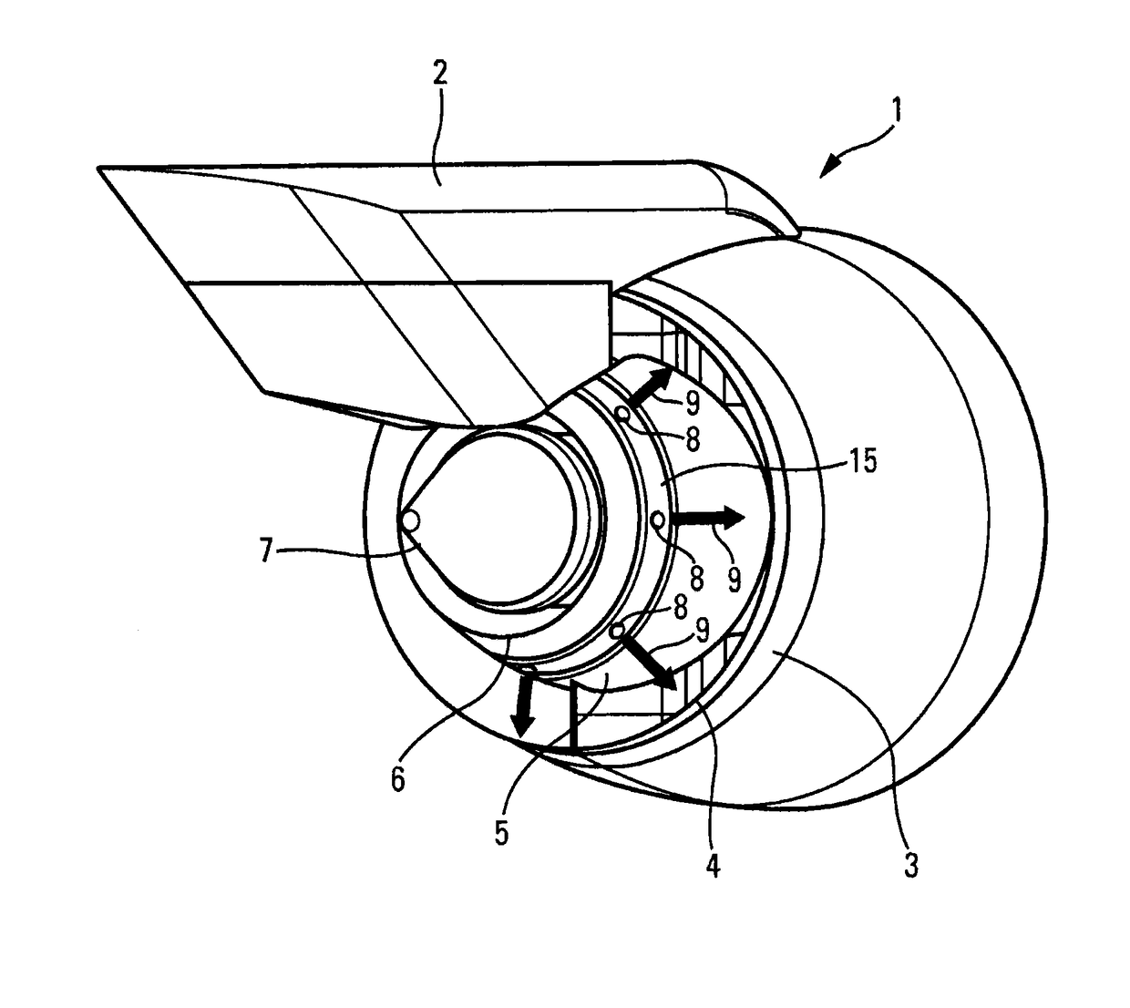
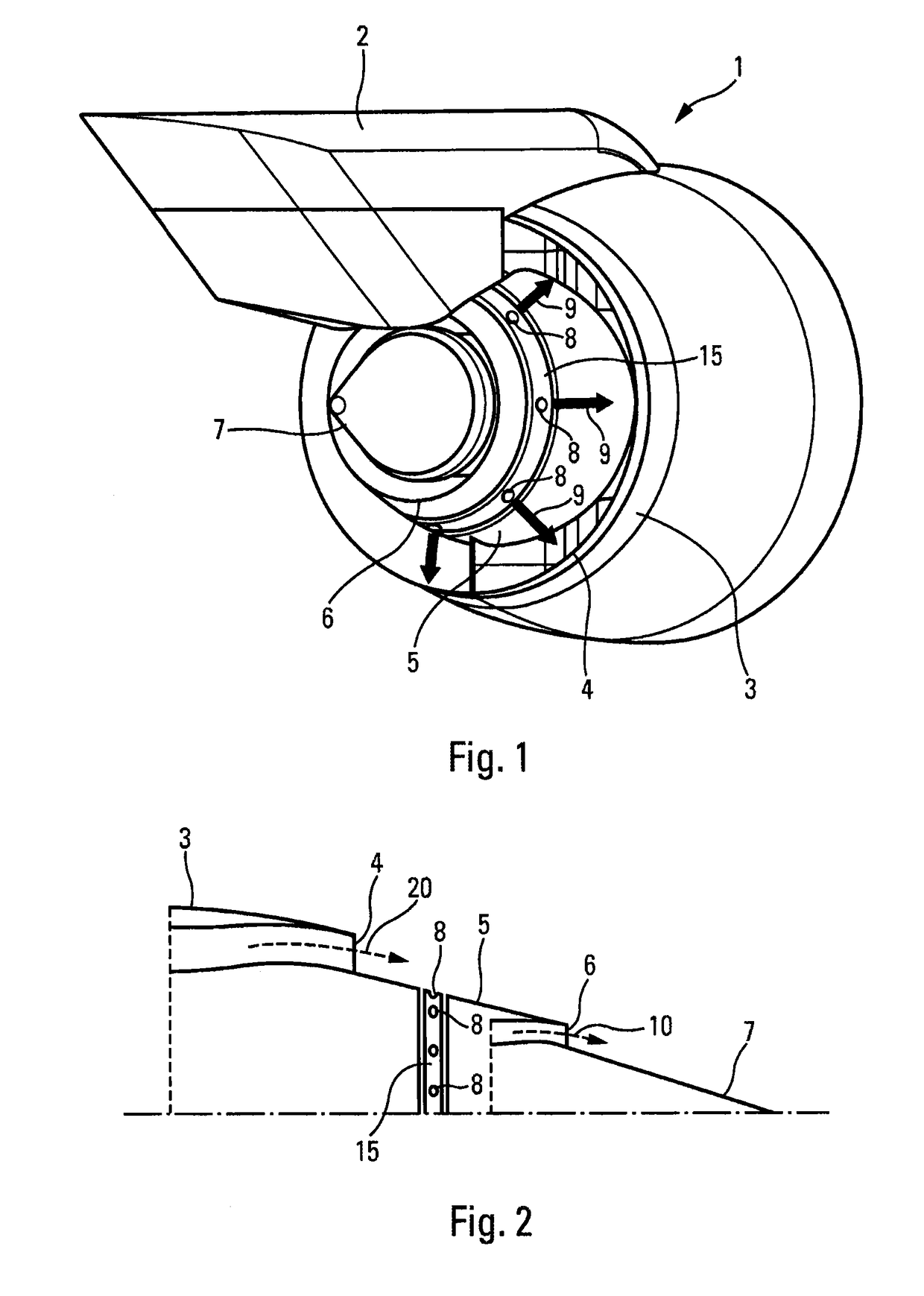
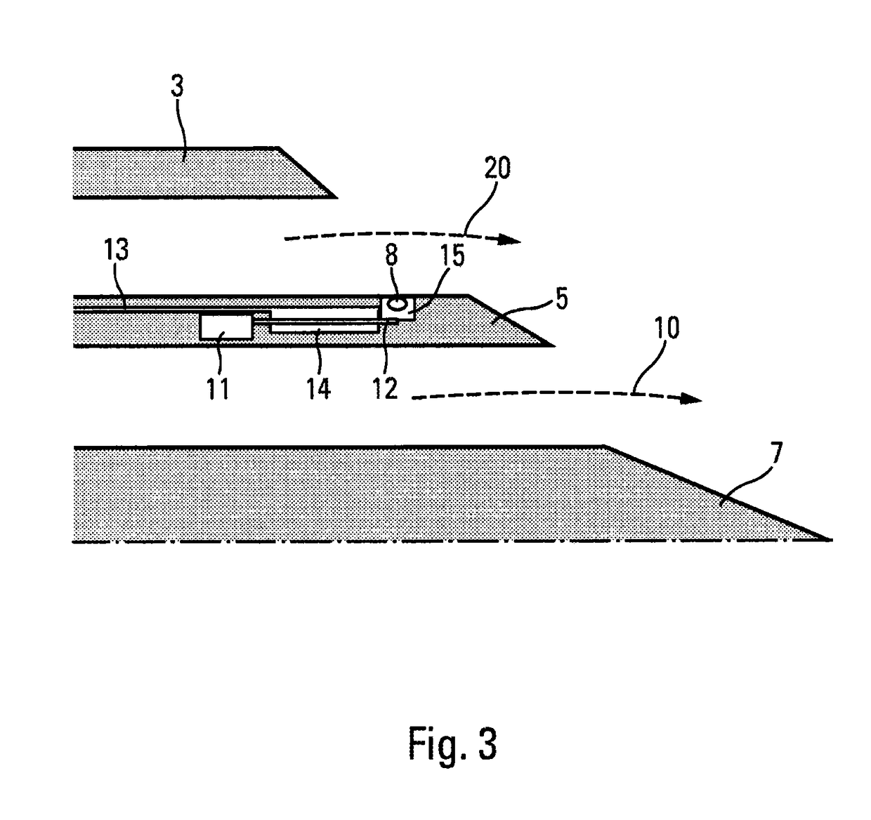
[0023]FIG. 1 shows a turbofan 1, with a high bypass ratio, mounted on the pylon 2 of an aircraft (not shown). The turbofan 1 comprises a nacelle, the front part of which surrounds the fan and the rear part, or secondary cowl 3, of which forms, with the external part of the primary cowl 5, the ejection nozzle 4 for the secondary stream. The primary body of the turbofan is enclosed in a series of cases terminating downstream with the primary cowl 5 which separates the primary and secondary streams. On the inside, the primary stream is channeled by the tail cone 7 which forms, with the internal part of the primary cowl 5, the ejection nozzle 6 for the primary stream.

[0024]The primary cowl 5 is cut circularly downstream of the secondary ejection nozzle 4, in order to leave space for a ring 15, the external face of which is located in the extension of the cowl such as to recreate continuity in the secondary stream. Unlike the primary cowl which is fixed, this ring is rotatable about the ...


PUM


Abstract

The invention relates to a primary cowl for a turbofan comprising a primary body generating a primary stream to be ejected through a primary nozzle, and a secondary body generating a secondary stream to be ejected through a secondary nozzle, the primary cowl being shaped so as to be positioned downstream from the primary body and to define, on the inside of the turbofan, the path followed by the primary stream downstream from the primary nozzle and, on the outside, the path followed by the secondary stream downstream from the secondary nozzle. The primary cowl comprises a coupling to a system for supplying a pressurized gas and at least one perforation for injecting the pressurized gas, through the perforation, into the secondary stream. The primary cowl preferably comprises a ring which has perforations and which is rotated about the axis of rotation of the turbofan.

Description

BACKGROUND OF THE INVENTION[0001]Field of the Invention[0002]The field of the present invention is that of turbine engines and more particularly that of devices for reducing the noise produced by these turbine engines.[0003]Description of the Related Art[0004]Commercial aircraft are generally provided with turbofans, which are made up of a gas turbine driving a ducted fan, this being generally placed upstream of the engine. The air mass sucked in by the engine is divided into a primary stream, which circulates in the gas turbine or primary body, and a secondary stream, which comes from the fan, the two streams being concentric. The primary stream exits the fan in order to move into the primary body where it is compressed again, heated in a combustion chamber, guided to successive stages of turbines, then ejected in a primary gas stream. The secondary stream is compressed by the ducted fan stage, then ejected directly without having been heated. The two streams can be ejected separat...

Claims


Application Information

Patent Timeline
Patent Type & Authority Patents(United States)
IPC IPC(8): F02K1/28F02K1/34F02K1/30F02K3/02F02K3/075F02K1/46F02K1/38
CPCF02K1/34F02K1/28F02K1/30F02K1/38F02K3/025F02K1/386F02K1/46F02K3/075Y02T50/671Y02T50/60
Inventor VUILLEMIN, ALEXANDRE ALFRED GASTONBODARD, GUILLAUMEAEBERLI, SEBASTIEN JEAN-PAUL
Owner SN DETUDE & DE CONSTR DE MOTEURS DAVIATION S N E C M A
Why Eureka
Try Eureka