Portable engine

a portable engine and engine body technology, applied in the direction of machines/engines, liquid fuel feeders, mechanical apparatus, etc., can solve the problems of troublesome operation, inability to extract fuel in the fuel tank, and inability to extract fuel on the bottom of the kerosene pump, etc., to achieve the effect of easy extraction of fuel

Inactive Publication Date: 2017-04-11
SUBARU CORP
View PDF30 Cites 3 Cited by
  • Summary
  • Abstract
  • Description
  • Claims
  • Application Information

AI Technical Summary

Benefits of technology

[0011]The present invention has been achieved in view of the above-described problems, and it is an object thereof to provide a portable engine capable of easily extracting fuel in a fuel tank to outside.

Problems solved by technology

The portable engine generator is used in various ways, and a portable engine generator used for ensuring a power supply in an emergency or an outdoor leisure, for example, may often be stored unused for relatively a long period of time.
A conventional engine generator is not provided with a dedicated structure for extracting fuel in a fuel tank, and therefore, the fuel is extracted with a kerosene pump after removing a cap on a fuel injection opening of the tank or the engine is driven needlessly until there is no more fuel in the fuel tank.
However, it may be not possible to extract the fuel remaining on the bottom with a kerosene pump if the shape of the tank is complicated and it is needed to operate the kerosene pump for many times, and hence the operation is troublesome.
On the other hand, driving an engine needlessly until there is no more fuel in the fuel tank is not preferable because an unnecessary cost burden is imposed on a user and carbon oxide, which is possibly resulting in a cause of global warming, is generated.
S56-57960 is designed to extract the fuel in a vaporizer, and thus, it cannot extract the fuel in the fuel tank.
Further, although the engine generator provided with a fuel cock described in JP-A No. 2001-27128 can prevent fuel from flowing into a cylinder from a fuel tank while carried it is not possible to extract the fuel in the fuel tank to outside.

Method used


Image

  • Portable engine
  • Portable engine
  • Portable engine

Examples


Embodiment Construction

[0024]With reference to the drawings, one implementation of the present invention will be described in detail below.

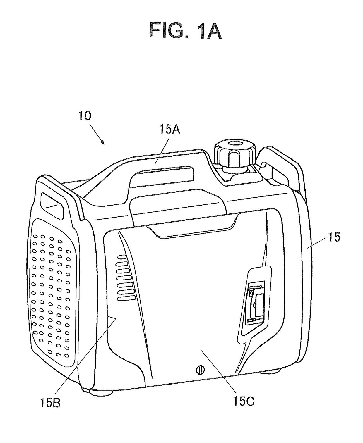
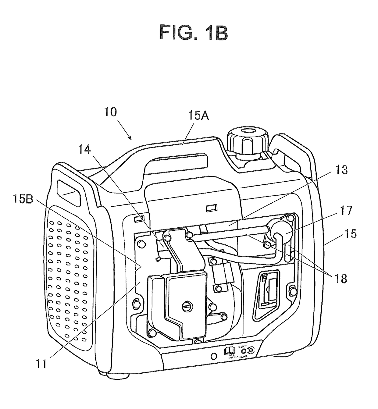
[0025]FIGS. 1A and 1B illustrate an overview of a portable engine generator which is an example of an engine to which the present invention is suitably applied. FIG. 1A is a perspective view illustrating a state where a side cover is attached, and FIG. 1B is a perspective view illustrating a state where the side cover is removed.

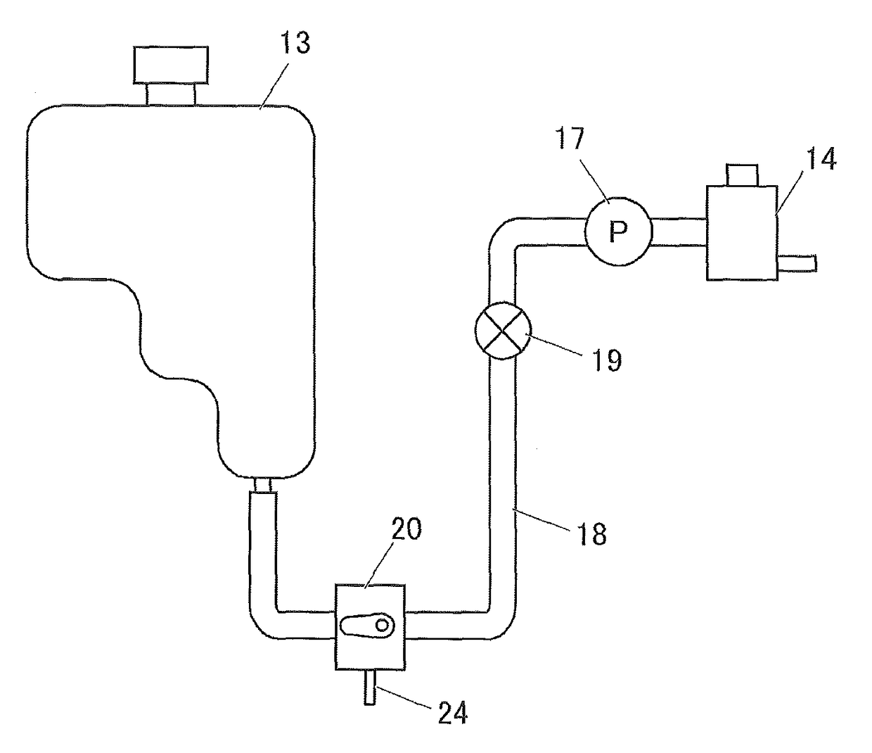
[0026]As illustrated in FIG. 1B, a portable engine generator 10 according to the present implementation includes an internal combustion engine 11 (hereinafter, referred to as “engine main body”) such as an air-cooled gasoline engine, and a generator (not illustrated) that is rotationally driven by the engine main body 11 to generate power. Further, the engine generator 10 includes: a fuel tank 13 to store fuel such as gasoline supplied to the engine main body 11; and a carburetor (vaporizer) 14 to vaporize the fuel supplied to the engine. A box...


PUM


Abstract

A portable engine includes: an internal combustion engine to burn fuel so as to output power; a fuel tank to store the fuel; a fuel pump to transfer the fuel from the fuel tank to the internal combustion engine; a U-shaped fuel pipe to transfer the fuel is disposed, and at a lowest portion of a fuel passage of the fuel pipe; and a fuel drainer capable of discharging the fuel in the fuel pipe to outside. The U-shaped fuel pipe is disposed between the fuel tank and the fuel pump, and the fuel drainer is disposed at a lowest site of a fuel passage of the fuel pipe.

Description

CROSS-REFERENCE TO RELATED APPLICATIONS[0001]The present application claims priority from Japanese Patent Application No. 2013-094885, filed on Apr. 30, 2013, the entire contents of which are hereby incorporated by reference.BACKGROUND[0002]1. Technical Field[0003]The present invention relates to a portable engine provided with a fuel tank, and in particular, relates to a technique suitably applied to a fuel drainer of a portable engine generator housed in a soundproof case.[0004]2. Related Art[0005]A portable engine generator is used for outdoor activities with no power supply available in the vicinity. The portable engine generator is used in various ways, and a portable engine generator used for ensuring a power supply in an emergency or an outdoor leisure, for example, may often be stored unused for relatively a long period of time. When the portable engine generator is stored for such a long period of time, it is recommended to extract fuel in a fuel tank to outside to prevent ...

Claims


Application Information

Patent Timeline
Patent Type & Authority Patents(United States)
IPC IPC(8): F02B43/08F02M37/00F02B63/02F02M37/04F02B77/13
CPCF02M37/0017F02B63/02F02B77/13F02M37/007
Inventor KUWATO, MAKOTOHIROTA, KENTARO
Owner SUBARU CORP
Why Eureka
Try Eureka