Oil level indicator for rotary wing aircraft transmission

a technology of oil level indicator and rotary wing aircraft, which is applied in the direction of liquid/fluent solid measurement, instruments, machines/engines, etc., can solve the problems of increasing the temperature of the gearbox, churning of the lubricant within the gearbox, and heat generation

Active Publication Date: 2017-04-11
SIKORSKY AIRCRAFT CORP
View PDF10 Cites 1 Cited by
  • Summary
  • Abstract
  • Description
  • Claims
  • Application Information

AI Technical Summary

Problems solved by technology

Lubricant within the gearbox is subject to churning where the lubricant hits the gears and to windage resulting from action of the gears throwing the lubricant.
The churning and windage, as well as the viscous drag of the lubricant, results in heat generation.
For example, if the gearbox includes an excessive amount of lubricant, churning may occur which ultimately increases the temperature of the gearbox.
If the gearbox has too little lubricant, the lubricant will degrade prematurely.
When the system is not positioned on a flat surface, however, the level of lubricant indicated by the indicator mechanism is affected, because the level is being measured outside of the system.

Method used


Image

  • Oil level indicator for rotary wing aircraft transmission
  • Oil level indicator for rotary wing aircraft transmission
  • Oil level indicator for rotary wing aircraft transmission

Examples


Embodiment Construction

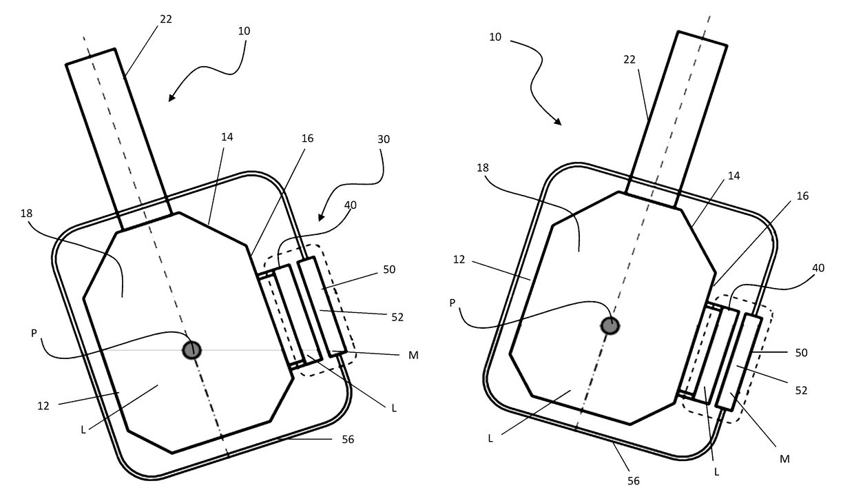
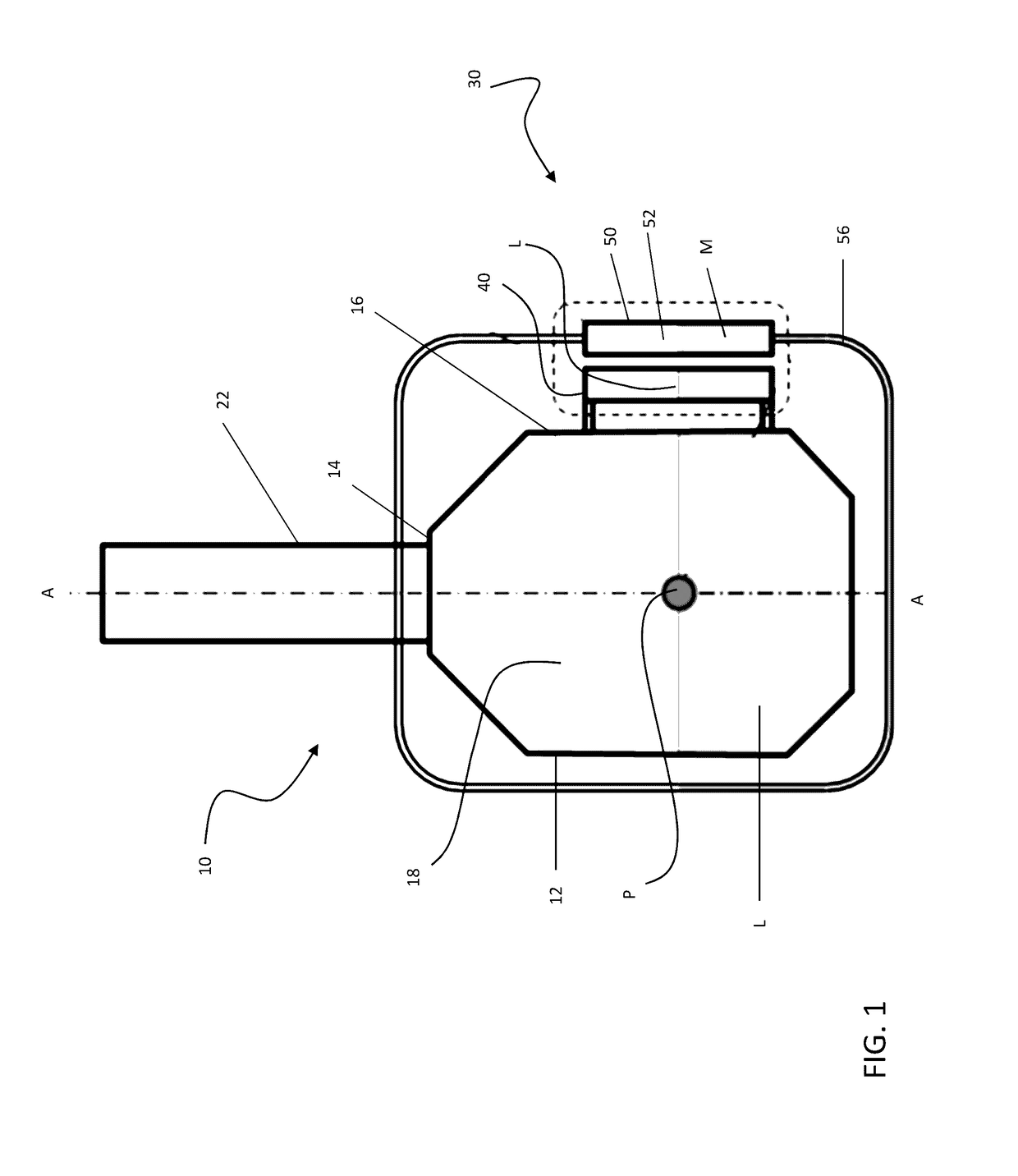
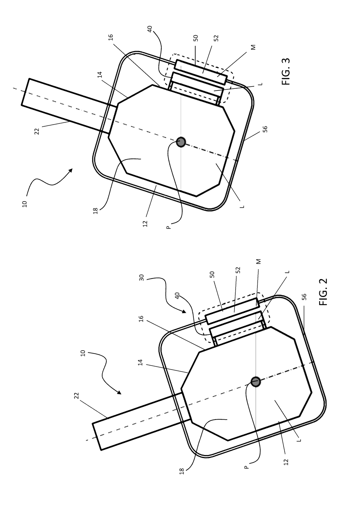
[0017]Referring now to FIG. 1, a portion of a transmission or propulsion system 10 for a rotary wing aircraft is illustrated and includes a gearbox housing 12 having an internal chamber 18 partially filled with a first fluid L, such as a lubricant for example. The first fluid L within the chamber 18 includes a generally central pivot point P defined by the shape of the gearbox housing 12. When the gearbox housing 12 is rotated about the pivot point P (see FIGS. 2 and 3), for example when the rotary wing aircraft is at an incline about either its roll or pitch axis, the level of the first fluid L at the pivot point P remains generally constant. Extending from a portion of the internal chamber 18 through an upper surface 14 of the gearbox housing 12 is a rotor shaft 22. In embodiments where the housing 12 is symmetrical, as shown in FIG., the axis of rotation A of the rotor shaft 22 intersects the pivot point P of the first fluid L in the internal chamber 18. However, the invention is...


PUM


Abstract

A fluid level sensor for determining an amount of first fluid in a system is provided including a first substantially transparent sight glass mounted outside and fluidly coupled to a portion of the system. A level of first fluid in the first sight glass is indicative of the amount of first fluid in the system. A second substantially transparent sight glass has an independent closed loop containing a second fluid. The second sight glass is positioned adjacent outside the system. A plane of the second sight glass is arranged adjacent to a pivot point of the first fluid within the system. A level of second fluid in the second sight glass is indicative of the amount of first fluid corresponding to normal operation of the system. A comparison of the level of first fluid in the first sight glass and the level of second fluid in the second sight glass indicates if the amount of first fluid in the system requires adjustment.

Description

BACKGROUND OF THE INVENTION[0001]This invention was made with Government support under Agreement N00019-06-C-0081 awarded by the Department of the Navy. The Government has certain rights in the invention.BACKGROUND OF THE INVENTION[0002]Exemplary embodiments of the invention generally relate to lubrication systems, and more particularly, to an indicator for determining the amount of lubrication in a lubrication system of an aircraft.[0003]A sealed gearbox having meshing gears, shaft bearing, and other components is provided with a continuous flow of lubricant in excess of that required for cooling. Lubricant within the gearbox is subject to churning where the lubricant hits the gears and to windage resulting from action of the gears throwing the lubricant. The churning and windage, as well as the viscous drag of the lubricant, results in heat generation. The amount of lubricant in the gearbox is critical for proper operation. For example, if the gearbox includes an excessive amount ...

Claims


Application Information

Patent Timeline
Patent Type & Authority Patents(United States)
IPC IPC(8): G01F23/02G01F23/00G01F22/00B64D33/00B64D35/00
CPCG01F23/02G01F22/00G01F23/0007G01F23/0046B64D33/00B64D35/00
Inventor GMIRYA, YURIY
Owner SIKORSKY AIRCRAFT CORP
Why Eureka
Try Eureka