Projector

a projector and optical element technology, applied in the field of projectors, can solve the problems of degrading display quality, insufficient effect for reducing speckles obtained by providing only equalizing optical elements, etc., and achieve the effect of reducing speckles and reducing variations in illuminance distribution

Active Publication Date: 2017-04-11
SEIKO EPSON CORP
View PDF3 Cites 1 Cited by
  • Summary
  • Abstract
  • Description
  • Claims
  • Application Information

AI Technical Summary

Benefits of technology

[0007]An advantage of some aspects of the invention is to provide a projector capable of sufficiently reducing the speckles, and thus superior in display quality.
[0010]According to the projector related to the aspect of the invention, in the exit pupil, the illuminance peak due to the zero-order light beam corresponding to the first light beam is disposed at a position different from a position of the illuminance peak due to the diffracted light beam corresponding to the second light beam. Thus, since the dispersibility of the plurality of illuminance peaks in the exit pupil of the projection optical system is enhanced, the variation in illuminance distribution becomes small, and the speckle can be reduced.
[0014]According to this configuration, since the direction in which the plurality of illuminance peaks due to the plurality of zero-order light beams is arranged coincide with the direction in which the plurality of light sources in a plane perpendicular to the illumination light axis is arranged, the arrangement direction of the plurality of light sources intersects with the arrangement direction of the plurality of illuminance peaks due to the plurality of diffracted light beams, namely the diffraction direction of the light beams. By using the illumination device having the plurality of light sources arranged as described above, the speckle can be reduced.
[0016]According to this configuration, since the direction in which the plurality of illuminance peaks due to the plurality of zero-order light beams is arranged coincide with the direction in which the plurality of lenses in a plane perpendicular to the illumination light axis is arranged, the arrangement direction of the plurality of lenses intersects with the arrangement direction of the plurality of illuminance peaks due to the plurality of diffracted light beams, namely the diffraction direction of the light beams. By using the lens array having the plurality of lenses arranged as described above, the speckle can be reduced.
[0018]According to this configuration, since the regularity of the arrangement of the plurality of illuminance peaks is broken, the variation in illuminance distribution becomes apparently small. As a result, the speckle can be reduced.

Problems solved by technology

This significantly degrades the display quality.
Although the projection video display device of Document 1 is equipped with the equalizing optical element, the effect for reducing the speckles obtained by merely providing the equalizing optical element is still insufficient.

Method used


Image

  • Projector
  • Projector
  • Projector

Examples


first embodiment

[0031]Hereinafter, a first embodiment of the invention will be explained using FIGS. 1, 2A, 2D, 2C, 3A, 3B, 3C, 4A, and 4B.

[0032]In the present embodiment, an example of a projector using an illumination device provided with a laser source will be described.

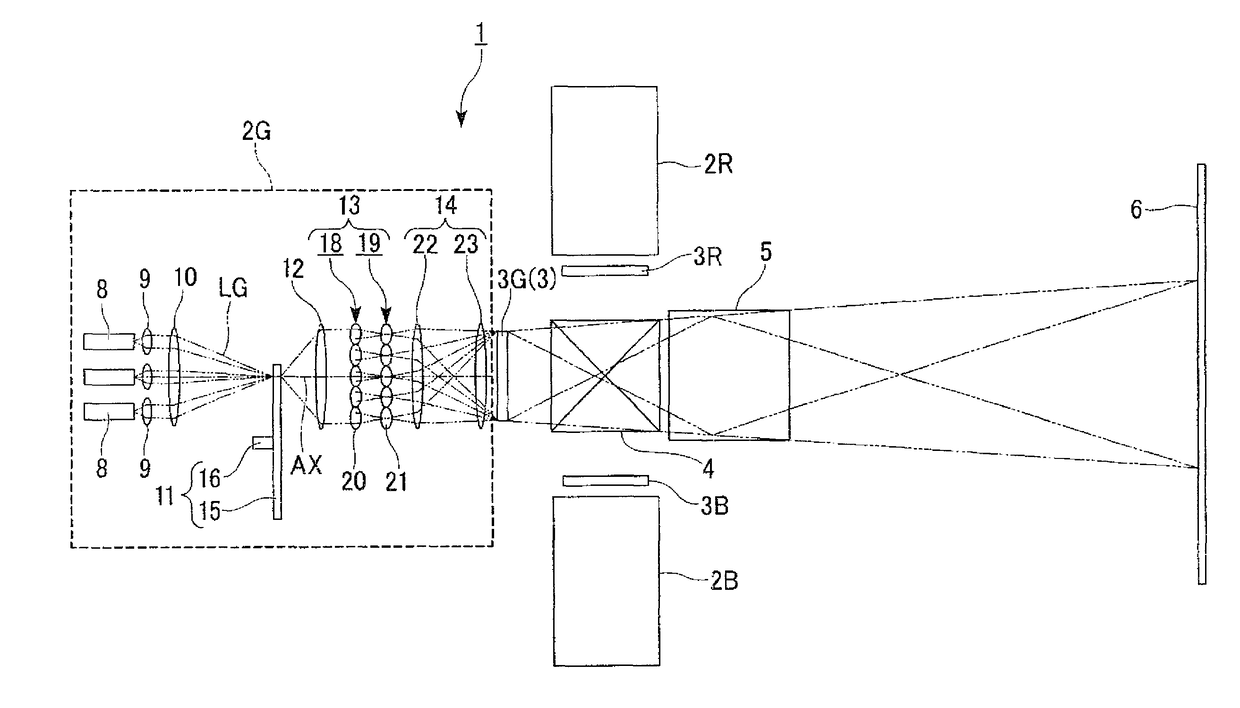
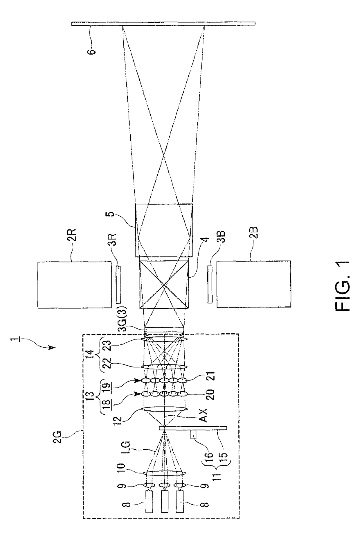
[0033]FIG. 1 is a schematic configuration diagram showing the projector according to the first embodiment.

[0034]It should be noted that in each the following drawings, the constituents are shown with the scale ratios of respective sizes set differently between the constituents in some cases in order to facilitate the visualization of each of the constituents.

[0035]As shown in FIG. 1, the projector 1 is provided with a red-light illumination device 2R, a green-light illumination device 2G, a blue-light illumination device 2B, a red-light liquid crystal light valve 3R, a green-light liquid crystal light valve 3G, a blue-light liquid crystal light valve 3B, a color combining element 4, and a projection optical system 5.

[0036]The red...

second embodiment

[0068]A second embodiment of the invention will hereinafter be explained using FIGS. 5 through 7.

[0069]The basic configuration of a projector 31 according to the second embodiment is roughly the same as that in the first embodiment, and the configuration of the illumination device is different from that of the first embodiment.

[0070]FIG. 5 is a schematic configuration diagram showing the projector 31 according to the second embodiment.

[0071]In FIG. 5, the constituents common to FIG. 1 used in the description of the first embodiment are denoted with the same reference symbols, and the detailed explanation thereof will be omitted.

[0072]As shown in FIG. 5, a green-light illumination device 32G of the second embodiment emits a plurality of green light beams, which include a first light beam and a second light beam, as the illumination light. The green-light illumination device 32G is provided with the plurality of laser sources 8, the plurality of collimating lenses 9, a diffractive opt...

third embodiment

[0077]A third embodiment of the invention will hereinafter be explained using FIGS. 8 and 9. The basic configuration of a projector according to the third embodiment is roughly the same as that in the first embodiment, and the configuration of the illumination device is different from that of the first embodiment.

[0078]FIG. 8 is a schematic configuration diagram showing the projector 41 according to the third embodiment. In FIG. 8, the constituents common to FIG. 1 used in the description of the first embodiment are denoted with the same reference symbols, and the detailed explanation thereof will be omitted.

[0079]As shown in FIG. 8, a green-light illumination device 420 of the third embodiment emits a plurality of green light beams, which include a first light beam and a second light beam, as the illumination light. The green-light illumination device 420 is provided with the plurality of laser sources 8, the plurality of collimating lenses 9, the lens array unit 13, and the overla...


PUM


Abstract

A projector includes an illumination device adapted to emit a plurality of light beams, which includes a first light beam and a second light beam, as illumination light, a liquid crystal light valve, and a projection optical system adapted to project image light, which is emitted from the liquid crystal light valve, on a screen. The image light is formed of a plurality of diffracted light beams and a plurality of zero-order light beams, which are generated by the illumination light and the liquid crystal light valve. In the exit pupil, an illuminance peak due to the zero-order light beam corresponding to the first light beam is disposed at a position different from a position of an illuminance peak due to the diffracted light beam corresponding to the second light beam.

Description

BACKGROUND[0001]1. Technical Field[0002]The present invention relates to a projector.[0003]2. Related Art[0004]Projectors using a laser source have an advantage that miniaturization of the device can be achieved, an advantage of being superior in color reproducibility, and advantage that instantaneous lighting can be performed, an advantage that the life of the light source is long, and other advantages. Incidentally, the laser beam emitted from the laser source is generally a coherent light beam. Therefore, in the projectors of this kind, there are some cases in which a speckled pattern caused by interference of the laser beams, a so-called speckle, is visually recognized on a screen. This significantly degrades the display quality.[0005]In the projector using a laser source, there are taken measures for suppressing the degradation of the display quality due to the speckle. In JP-A-2011-180281 (Document 1), there is disclosed a projection video display device equipped with an equal...

Claims


Application Information

Patent Timeline
Patent Type & Authority Patents(United States)
IPC IPC(8): G03B21/00H04N9/31G02B27/48
CPCG02B27/48H04N9/3161
Inventor EGAWA, AKIRA
Owner SEIKO EPSON CORP
Why Eureka
Try Eureka