Downhole elastic anisotropy measurements

a technology of elastic anisotropy and measurement method, which is applied in the field of downhole elastic anisotropy measurement, can solve problems such as inferences that can be problematic, and achieve the effect of improving the reliability and accuracy of determined elastic constants

Active Publication Date: 2017-04-18
SCHLUMBERGER TECH CORP
View PDF21 Cites 7 Cited by
  • Summary
  • Abstract
  • Description
  • Claims
  • Application Information

AI Technical Summary

Benefits of technology

[0007]The disclosed embodiments may provide various technical advantages. For example, the disclosed logging apparatus and method enable the five elastic constants of a transversely isotropic formation to be directly determined without using geophysical inferences or assumptions. Moreover, these constants may be determined and transmitted to the surface in real time while drilling. Furthermore, in certain embodiments, a sufficient number of acoustic measurements may be made so as to over specify the system and improve the reliability and accuracy of the determined elastic constants.

Problems solved by technology

However, conventional axial acoustic measurements only enable three (or occasionally four) of these five elastic constants to be determined.
The remaining constant(s) are sometimes inferred from various assumptions about the geophysics of the formation; however, such inferences can be problematic.

Method used


Image

  • Downhole elastic anisotropy measurements
  • Downhole elastic anisotropy measurements
  • Downhole elastic anisotropy measurements

Examples


embodiment 200

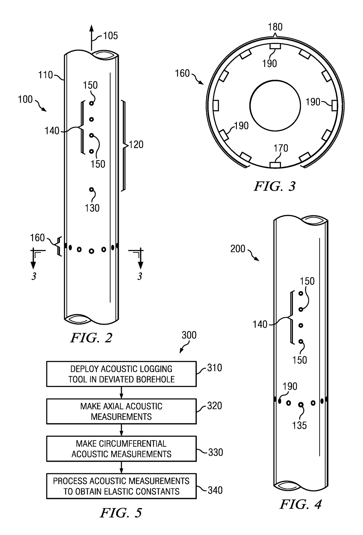
[0022]FIG. 4 depicts another downhole acoustic logging tool embodiment 200. Acoustic logging tool 200 is similar to acoustic logging tool 100 in that it includes an axial acoustic measurement module and a circumferential measurement module; however acoustic logging tool 200 differs from acoustic logging tool 100 in that the axial and circumferential measurement modules share a common transmitter 135. As depicted the transmitter 135 is axially spaced apart from the linear array 140 of acoustic receivers 150 and circumferentially spaced apart from the circumferential array of acoustic receivers 190. Transmitter 135 is also deployed at a common circumferential position with the linear array 140 of acoustic receivers 150 and a common axial position with the circumferential array of acoustic receivers 190. In this way a single transmitter firing may be used to obtain both axial and circumferential acoustic logging data. In other words the acoustic signals propagated by transmitter 135 ma...

embodiment 300

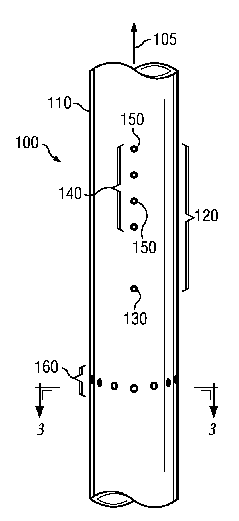
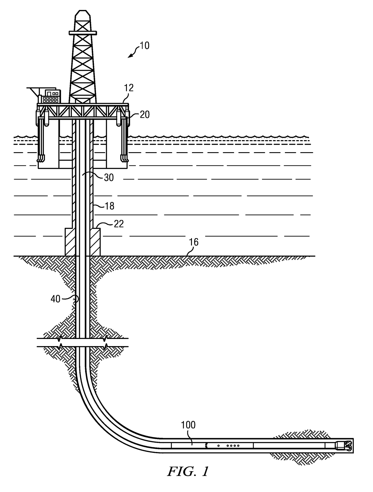
[0024]FIG. 5 depicts a flow chart of one disclosed method embodiment 300 for measuring the five elastic constants of a transverse isotropic media. An acoustic logging tool such as logging tool 100 (FIGS. 2 and 3) or logging tool 200 (FIG. 4) may be deployed in a deviated subterranean borehole at 310 (by deviated it is meant that the borehole is not aligned with the vertical axis (also referred to in the art as a symmetry axis) of a transversely isotropic medium or is non-vertical in a VTI medium). Axial acoustic measurements are made at 320 to obtain compressional and shear wave velocities for acoustic energy propagating in the axial direction. Circumferential acoustic measurements are made at 330 to obtain at least one of a compressional wave velocity or a shear wave velocity for acoustic energy propagating in the cross-axial direction (about the circumference of the acoustic measurement tool). It will be understood that the axial acoustic measurements and the circumferential acous...


PUM


Abstract

A downhole acoustic logging tool includes at least one acoustic transmitter and first and second arrays of acoustic receivers deployed on a tool body. The first array of acoustic receivers includes a plurality of axially spaced apart acoustic receivers and the second array of acoustic receivers includes a plurality of circumferentially spaced apart acoustic receivers. A method for making downhole acoustic logging measurements of a subterranean formation includes causing an acoustic logging tool to obtain axial acoustic logging measurements and circumferential acoustic logging measurements. The axial acoustic logging measurements and the circumferential acoustic logging measurements are then processed to compute each of five elastic constants of a transversely isotropic medium.

Description

CROSS REFERENCE TO RELATED APPLICATIONS[0001]None.FIELD OF THE INVENTION[0002]Disclosed embodiments relate generally to downhole acoustic measurements and more particularly to the determination of subsurface elastic anisotropy using borehole acoustic measurements having wave propagation in both the axial and circumferential directions.BACKGROUND INFORMATION[0003]The use of acoustic measurement systems in prior art downhole applications, such as logging while drilling (LWD) and wireline logging applications is well known. In one application, acoustic signals may be generated at one or more transmitters deployed in the borehole. These acoustic signals may then be received at an array of longitudinally spaced receivers deployed in the borehole. Acoustic logging in this manner provides an important set of borehole data and is commonly used in both LWD and wireline applications to determine compressional and shear wave velocities (also referred in the art in terms of their slowness value...

Claims


Application Information

Patent Timeline
Patent Type & Authority Patents(United States)
IPC IPC(8): G01V1/44G01V1/48G01V1/46
CPCG01V1/44G01V1/46G01V1/48G01V2200/16G01V2210/6222G01V2210/6242
Inventor PRIOUL, ROMAIN C. A.JOHNSON, DAVID L.D'ANGELO, RALPH M.
Owner SCHLUMBERGER TECH CORP
Why Eureka
Try Eureka