Unlock instant, AI-driven research and patent intelligence for your innovation.

System and method for I/O optimized data migration between high performance computing entities and a data storage supported by a de-clustered raid (DCR)architecture with vertical execution of I/O commands

a data storage and high-performance computing technology, applied in the direction of coding, instruments, code conversion, etc., can solve the problems of increasing the cpu load of the server, affecting the performance of the server, and the drive caches of a single drive overflowing, so as to prevent the on-board cache buffer from overflowing, the effect of optimizing the i/o operation

Active Publication Date: 2017-04-18
DATADIRECT NETWORKS
View PDF2 Cites 11 Cited by
  • Summary
  • Abstract
  • Description
  • Claims
  • Application Information

AI Technical Summary

Benefits of technology

The present invention is a data migration system and method that uses a de-clustered RAID (DCR) storage system with a Vertical Rotation DCR approach. This results in optimized input / output operations, increased sustained data transfer rates, and prevents cache buffer overflow.

Problems solved by technology

Unfortunately, even with the rotation speed of 15 K RPM and the seek time of the head of about 8 ms, most of contemporary disk drives can only maintain a sustained transfer rate of about 143 MBs (Megabits per second).
However, once again this raises the issue of overflowing the drive caches for a single drive after approximately 133 ms of the I / O operation.
As minor an effort as it might be to merge the VDs, it still increases the CPU load for the servers and adds complexity to their management, especially in a server de-clustered environment.
Linux and MS Windows can stripe VDs together but they also run on external servers, which complicates the system structure and operation.

Method used


Image

  • System and method for I/O optimized data migration between high performance computing entities and a data storage supported by a de-clustered raid (DCR)architecture with vertical execution of I/O commands
  • System and method for I/O optimized data migration between high performance computing entities and a data storage supported by a de-clustered raid (DCR)architecture with vertical execution of I/O commands
  • System and method for I/O optimized data migration between high performance computing entities and a data storage supported by a de-clustered raid (DCR)architecture with vertical execution of I/O commands

Examples


Embodiment Construction

[0077]FIG. 2 depicts a simplified representation of the subject de-clustered RAID (DCR) system 20 supporting data migration between the Client Compute Nodes 22 and a Redundant Array of (Inexpensive) Independent Disks (RAID) storage sub-system 24. Shown in FIG. 2 is an exemplary system architecture, while numerous other implementations supporting data migration between data generating entities and RAID storage devices are contemplated in the scope of the present invention.

[0078]The compute nodes 22 may be arranged in computing groups, or computer clusters, to perform complex computations of various types. The operation of the compute nodes depends on the system application. They may function as servers, super computing clusters, etc., and have the capacity to “write” by outputting data, as well as “read” from the storage sub-system 24, or an external memory, as well as any other device. In the present description the above-presented devices will be intermittently referenced further h...


PUM


Abstract

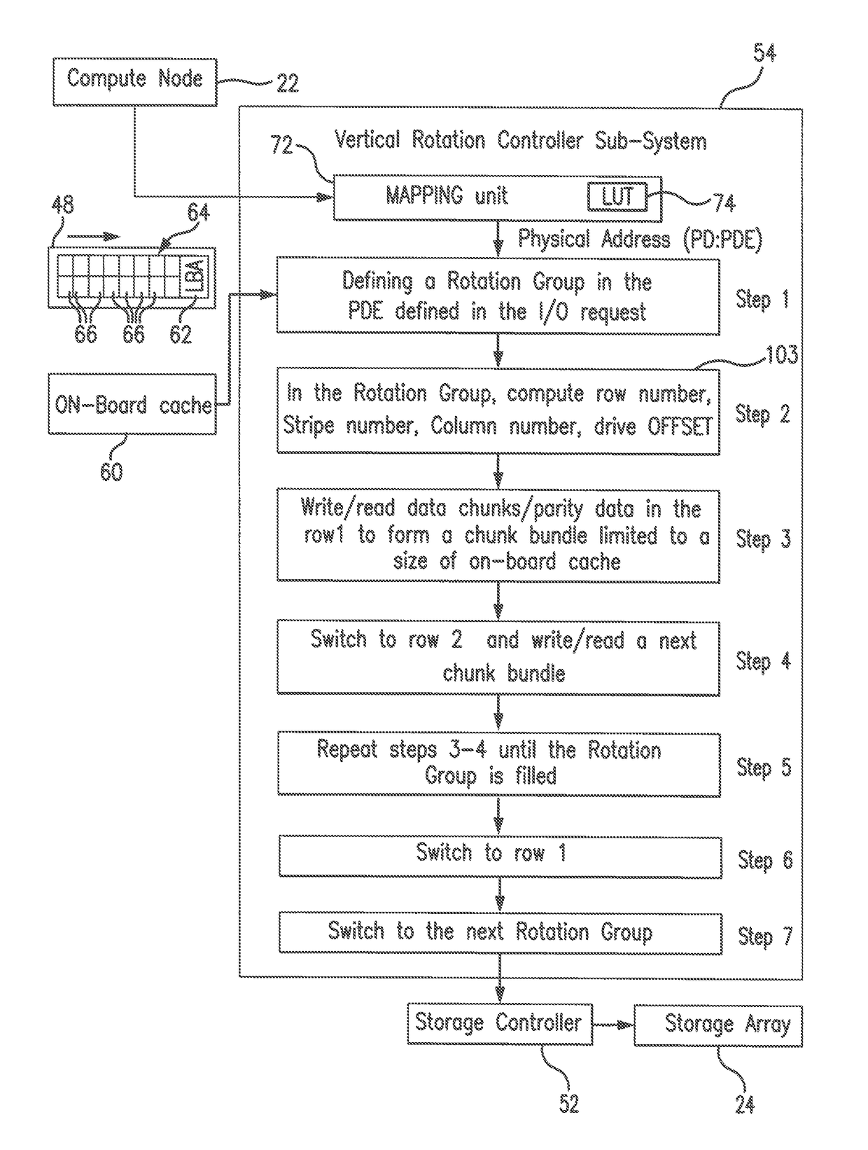
A data storage system employs a de-clustered RAID (DCR) organization with a Vertical Rotation approach to prevent overflow of cache buffers. The Vertical Rotation Controller limits the size of the I / O operation relative to a respective Physical Disk Extent (PDE) to the cache buffer, and writes / reads a computed parity stripe matching the size of the cache, to form chunk bundles in the PDEs. When a bundle is filled in a first PDE residing at a first row, a PDE residing at a second row vertically displaced from the first row is engaged for forming another bundle. The process continues until all PDEs in a Vertical Rotation Group (VRG) are filled, or continues to a next VRG vertically displaced from a previous one to end I / O requesting.

Description

FIELD OF THE INVENTION[0001]The present invention is directed to data migration between high performance computing cluster architectures (data generating entities) and data storage media. Particularly, the present invention relates to a data migration technique rendering optimized I / O activity by using a concept of a Vertical Rotation in de-clustered RAID (DCR) architectures.[0002]In its overall concept, the present invention relates to a de-clustered RAID (DCR) data storage organization forming a 2-dimensional DCR pool, which is a collection of Physical Disk Extents (PDEs) arranged in rows and columns, where each parity stripe is striped at respective PDEs constituting a row. This de-clustered RAID organization permits to leverage a vast number of drives for I / O operations and prevents the on-board cache buffer from overflow. For each PDE of interest, a Vertical DCR rotation is performed by reading from (or writing to) only a predetermined portion (not exceeding a size of an on-boa...

Claims


Application Information

Patent Timeline
IPC IPC(8): H03M13/00G06F11/10H04L29/08G06F3/06
CPCG06F11/1076H04L67/1095G06F3/0619G06F3/064G06F3/0689H04L67/1097G06F3/061G06F3/0647
Inventor PARKHURST, MICHEAL S.
Owner DATADIRECT NETWORKS