Method for ion source component cleaning

a technology of ion source components and cleaning methods, which is applied in the direction of vacuum evaporation coating, cleaning of hollow articles, coatings, etc., can solve the problems of frequent downtime, accumulated residue deposits that interfere with the successful operation of ion source, and reduce tool utilization, so as to improve tool utilization and cleaning operation speed, the effect of improving the utilization ra

Inactive Publication Date: 2017-04-18
PRAXAIR TECH INC
View PDF35 Cites 0 Cited by
  • Summary
  • Abstract
  • Description
  • Claims
  • Application Information

AI Technical Summary

Benefits of technology

[0020]The method of this invention provides higher removal rates than other known processes such as NF3 based processes for residue deposits formed during carborane implantation. The implementation of the method of this invention can enable customers to perform the desired cleaning operation faster and hence improve tool utilization. For example, users can gain an additional 1 hour of tool utilization per day by replacing NF3 based cleaning with F2 / Ar / O2 based cleaning process for carborane deposit removal in accordance with this invention. Faster cleaning operation can also result in less usage of cleaning gas and hence less frequent gas cylinder replacements. Thus, the users can further reduce tool downtime and safety concerns experienced during gas cylinder replacement.

Problems solved by technology

A problem with the ion implantation process involves deposition of gas material residues on the surfaces of the ion source chamber and components contained within the ion source chamber.
This can result in accumulated residue deposits that interfere with the successful operation of the ion source chamber, for example, electrical short circuits caused from residue deposits formed on low voltage insulators in the ion source chamber and energetic high voltage sparking caused from residue deposits formed on insulators in the ion source chamber.
The residue deposits can adversely impact the normal operation of the ion implanter, cause frequent downtime and reduce tool utilization.
Safety issues can also arise due to the emission of toxic or corrosive vapors when the ion source chamber and components contained within the ion source chamber are removed for cleaning.

Method used


Image

  • Method for ion source component cleaning
  • Method for ion source component cleaning
  • Method for ion source component cleaning

Examples


example 1

[0060]The performance of NF3 cleaning gas with different variations of cleaning gas chemistry used in this invention was compared. Under similar processing conditions, F2 / Ar and F2 / Ar / O2 mix demonstrated better removal rates than NF3 (see Tables A and B below). For the thermally activated cleaning process, F2 / Ar / O2 resulted in greater than 2× faster residue deposit removal rate even at lower temperature. Also, when operated under a combination of plasma and thermal activation, F2 / Ar / O2 based chemistry exhibited better removal rates than NF3 based chemistry. In addition, due to lower bond dissociation energy of F—F bonds in F2 compared to N—F bonds in NF3, less plasma power is required to sustain fully dissociated F2 plasma in comparison to NF3 plasma. Higher residue deposit removal rates in combination with low power requirements offer the user a wider process window to perform desired cleaning operation.

[0061]

TABLE AActivation Mode: ThermalO2 / F2 molPressureTemperatureRemoval RateCl...

example 2

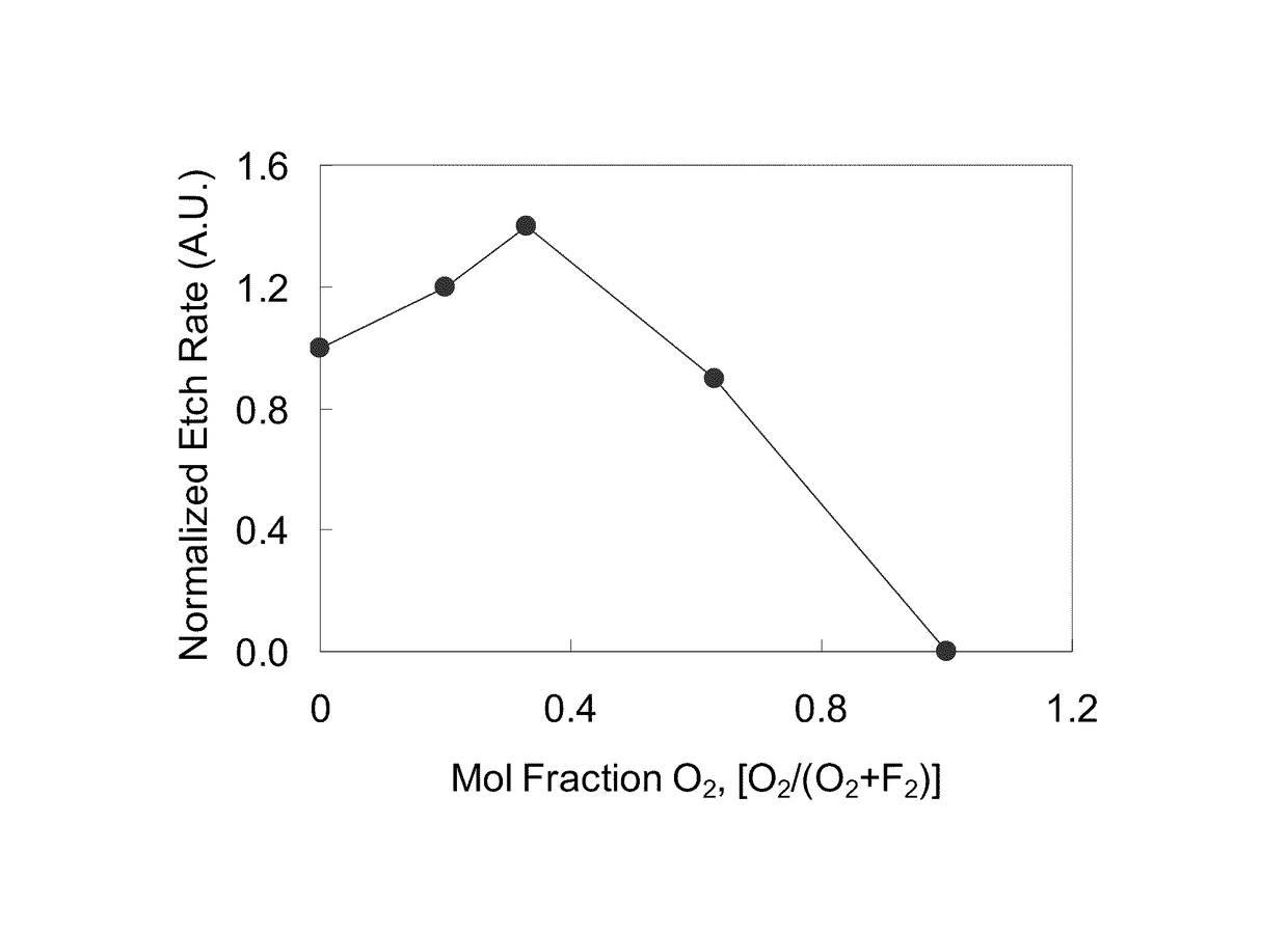
[0063]Experiments were conducted to evaluate removal rate of deposits from carborane dopant gas at different operating conditions. FIG. 4 presents removal rate observed at different flow rates of F2 / O2 / Ar mix (F2:O2:Ar-0.18:0.09:0.73) and F2 / Ar mix (F2:Ar-0.20:0.80). The mix compositions used in these experiments are:

[0064]F2 / O2 / Ar mix: F2:O2:Ar=0.18:0.09:0.73, i.e., F2 / [F2+Ar]=0.20 and O2 / [O2+F2]=0.33

[0065]F2 / Ar mix: F2:Ar=0.20:0.80, i.e. F2 / [F2+Ar]=0.20

[0066]FIG. 4 depicts the effect of cleaning gas flow and chamber pressure on removal rate. Pressure values listed beside each data point is the chamber pressure during corresponding experiment. It is observed that for both F2 / Ar and F2 / O2 / Ar mix removal rate drops by only about 1.9× and about 1.6× respectively with an about 5× reduction in cleaning gas flow (and corresponding chamber pressure) thus indicating more efficient utilization of cleaning gas in low flow-low pressure mode. It is also desirable to maintain low pressure (less...


PUM

PropertyMeasurementUnit
mole ratioaaaaaaaaaa
temperatureaaaaaaaaaa

Abstract

This invention relates in part to a method for cleaning an ion source component of an ion implanter used in semiconductor and microelectronic manufacturing. The ion source component includes an ionization chamber and one or more components contained within the ionization chamber. The interior of the ionization chamber and / or the one or more components contained within the ionization chamber have at least some deposits thereon of elements contained within a dopant gas, e.g., carborane (C2B10H12). The method involves introducing a cleaning gas into the ionization chamber, and reacting the cleaning gas with the deposits under conditions sufficient to remove at least a portion of the deposits from the interior of the ionization chamber and / or from the one or more components contained within the ionization chamber. The cleaning gas is a mixture of F2, one or more inert gases selected from noble gases and / or nitrogen, and optionally O2, or a mixture of an oxygen / fluorine-containing gas and one or more inert gases selected from noble gases and / or nitrogen. The deposits adversely impact the normal operation of the ion implanter causing frequent down time and reducing tool utilization.

Description

FIELD OF THE INVENTION[0001]This invention relates in part to a method for cleaning an ion source component of an ion implanter used in semiconductor and microelectronic manufacturing. The method involves removing deposits formed during dopant implantation using a cleaning gas mixture. The deposits adversely impact the normal operation of the ion implanter causing frequent down time and reducing tool utilization.BACKGROUND OF THE INVENTION[0002]Ion implantation is an important process in semiconductor / microelectronic manufacturing. The ion implantation process is used in integrated circuit fabrication to introduce dopant impurities into semiconductor wafers. The desired dopant impurities are introduced into semiconductor wafers to form doped regions at a desired depth. The dopant impurities are selected to bond with the semiconductor wafer material to create electrical carriers and thereby alter the electrical conductivity of the semiconductor wafer material. The concentration of do...

Claims


Application Information

Patent Timeline
Patent Type & Authority Patents(United States)
IPC IPC(8): B08B7/00C23C14/48C23C14/56H01J37/317B08B9/00H01J37/08H01J37/32
CPCH01J37/3171C23C14/48C23C14/564H01J37/08H01J37/32412H01J37/32862H01J2237/022
Inventor SINHA, ASHWINICAMPEAU, SERGE MARIUSBROWN, LLOYD ANTHONY
Owner PRAXAIR TECH INC
Why Eureka
Try Eureka