Heat storage member for canister

a technology of canisters and heat storage members, which is applied in the direction of mechanical equipment, machines/engines, transportation and packaging, etc., can solve the problems of difficult to efficiently conduct heat from the outer space to the phase-change material through the heat storage member, and the effect of reducing the effect of temperature alteration is unstable, and achieves the effect of preventing the effect of temperature alteration, stable heat storage efficiency, and stable thermal conductivity from a space surrounding

Inactive Publication Date: 2017-04-25
AISAN IND CO LTD
View PDF16 Cites 0 Cited by
  • Summary
  • Abstract
  • Description
  • Claims
  • Application Information

AI Technical Summary

Benefits of technology

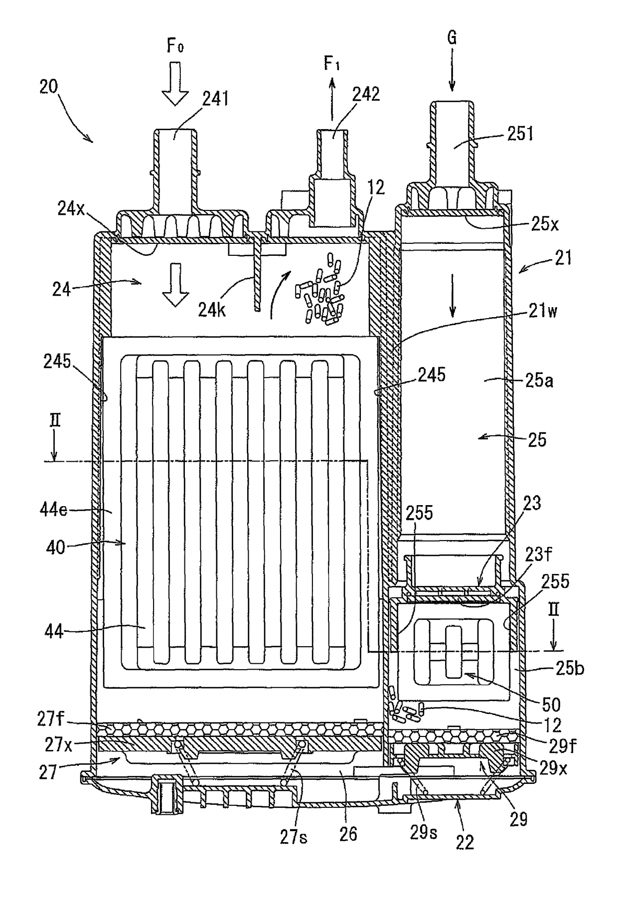
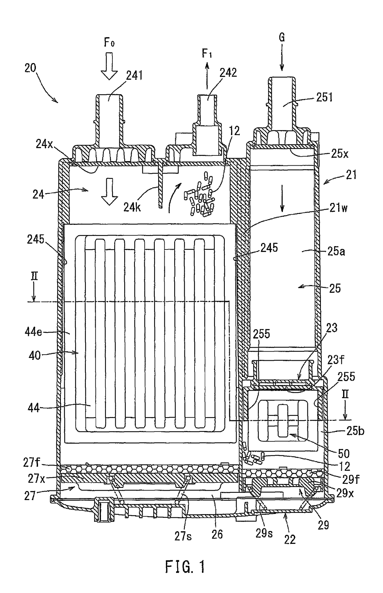
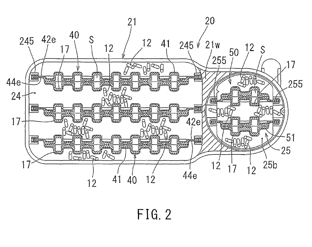
[0007]In accordance with this aspect, when the temperature of the phase-change material reaches at the melting point, the phase-change material does not become liquid completely but becomes semisolid gel state such that the phase-change material can retain its shape and does not move therefrom when inertial force is applied to the phase-change material during driving. Accordingly, because a contact position and a contact area between the sealed container and the phase-change material are always maintained, thermal conductivity from a space surrounding the heat storage member to the phase-change material via the sealed container is stable, and a heat storage efficiency (i.e., prevention effect in temperature alteration) is also stable. Further, because the phase-change material can retain its shape at the melting point, the space capable of compensating for volume alteration of the phase-change material caused by phase-change is formed at the center of the inner space of the sealed container and the phase-change material is disposed along the entire inner surface of the sealed container in order to maximize the contact area between the phase-change material and the sealed container. Accordingly, heat can be efficiently transferred from the outside to the phase-change material throughout the heat storage member.

Problems solved by technology

Therefore, thermal conductivity from an outer space around the heat storage member to the phase-change material via the sealed container varies, so that a heat storage effect (i.e., an effect of decrease in temperature alteration) is unstable.
Accordingly, there is always a part of the sealed container not contacting the phase-change material, so that it is difficult to efficiently conduct heat from the outer space to the phase-change material throughout the heat storage member.

Method used


Image

  • Heat storage member for canister
  • Heat storage member for canister
  • Heat storage member for canister

Examples


Embodiment Construction

[0014]Each of the additional features and teachings disclosed above and below may be utilized separately or in conjunction with other features and teachings to provide improved heat storage members. Representative examples, which utilize many of these additional features and teachings both separately and in conjunction with one another, will now be described in detail with reference to the attached drawings. This detailed description is merely intended to teach a person of skilled in the art further details for practicing preferred aspects of the present teachings and is not intended to limit the scope of the invention. Only the claims define the scope of the claimed invention. Therefore, combinations of features and steps disclosed in the following detailed description may not be necessary to practice the invention in the broadest sense, and are instead taught merely to particularly describe representative examples. Moreover, various features of the representative examples and the ...


PUM


Abstract

A heat storage member housed in a canister together with an adsorbent capable of adsorbing fuel vapor has a sealed container and a phase-change material housed in the sealed container. The phase-change material becomes semisolid gel state at the melting point of the phase-change material. The phase-change material is disposed along an entire inner surface of the sealed container such that a space capable of compensating for volume alteration of the phase-change material caused by phase-change is formed at a center of an inner space of the sealed container.

Description

CROSS-REFERENCE TO RELATED APPLICATIONS[0001]This application claims priority to Japanese patent application serial number 2013-216280, filed Oct. 17, 2013, the contents of which are incorporated herein by reference in their entirety for all purposes.BACKGROUND[0002]This disclosure relates to heat storage members for canisters. The heat storage members and phase-change material are housed in the canister configured to adsorb fuel vapor, which has vaporized in a fuel tank. The phase-change materials decrease temperature alteration in the canister by using latent heat generated during solidification or melting.[0003]Japanese Laid-Open Patent Publication No. 2009-215938 belonging to the applicant of this application discloses heat storage members. In Japanese Laid-Open Patent Publication No. 2009-215938, for example, hexadecane (C16H34) having the melting point at 18° C. is used as the phase-change material housed in the sealed container. This phase-change material changes to liquid at...

Claims


Application Information

Patent Timeline
Patent Type & Authority Patents(United States)
IPC IPC(8): F02M25/08B60K15/035
CPCF02M25/0854B60K2015/03514F02M2025/0881
Inventor MAKINO, KATSUHIKO
Owner AISAN IND CO LTD
Why Eureka
Try Eureka