Optical connector ferrule
a technology of optical connectors and ferrules, applied in the field of optical connector ferrules, can solve problems such as increased transmission loss, and achieve the effect of suppressing misalignment of optical paths
- Summary
- Abstract
- Description
- Claims
- Application Information
AI Technical Summary
Benefits of technology
Problems solved by technology
Method used
Image


Examples
first embodiment
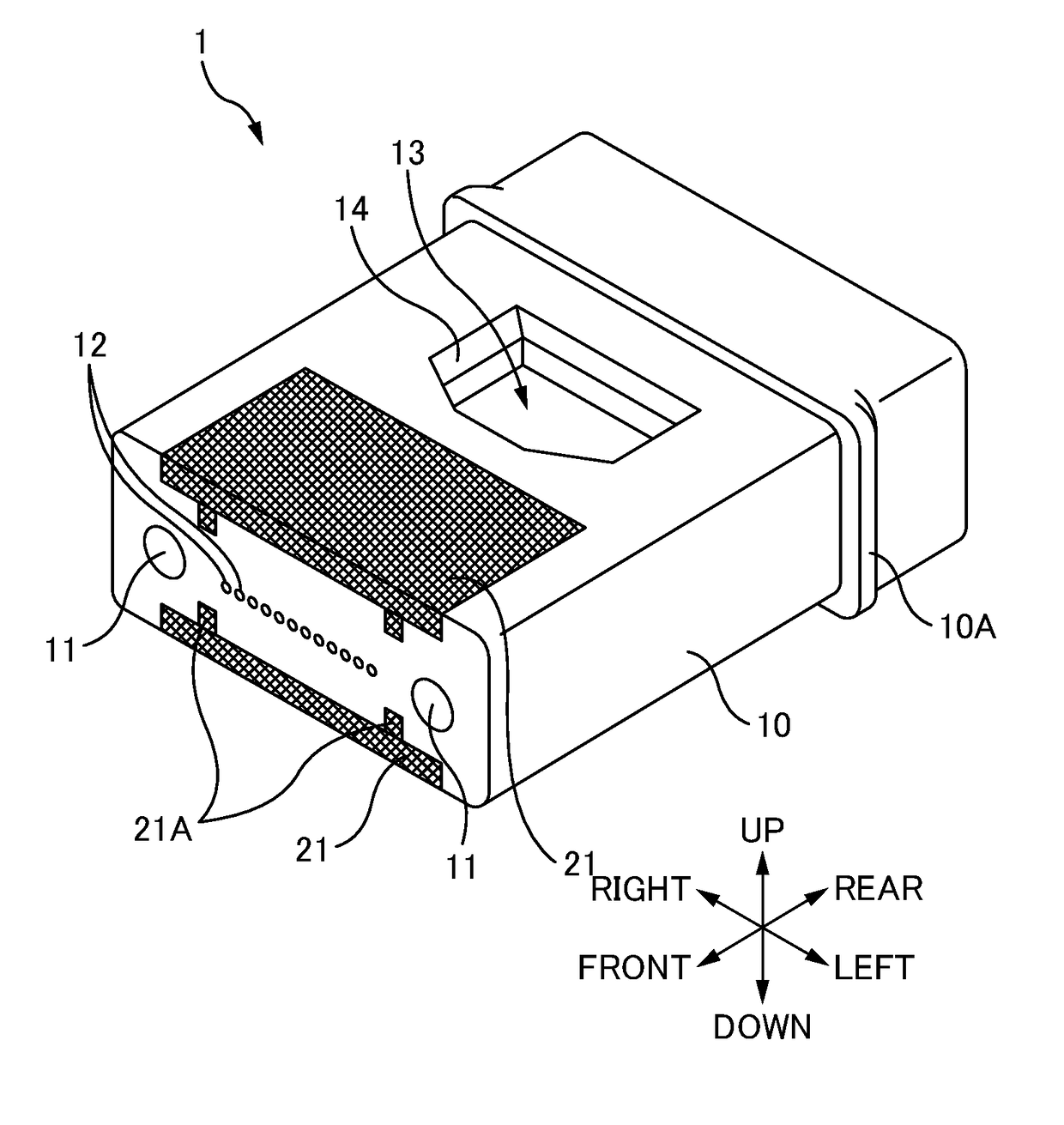
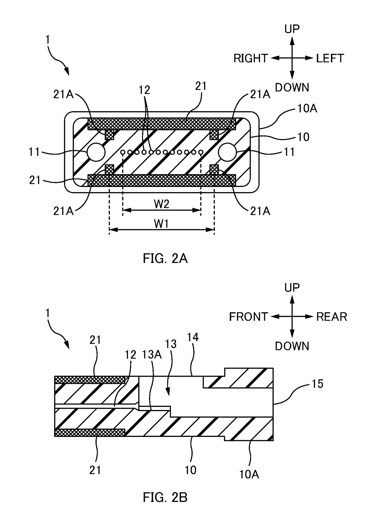
[0030]FIG. 1 is a perspective view of an optical connector ferrule 1 according to the first embodiment. FIG. 2A and FIG. 2B are sectional views of the optical connector ferrule 1 according to the first embodiment. The optical connector ferrule 1 according to the first embodiment is an MT connector equivalent to the F12 type multi-core optical fiber connector defined in Japan Industrial Standard (JIS) C 5981 (or, F15 type optical fiber connector defined in JIS C 5984.)
[0031]The directions will be defined as illustrated in the figures. To be specific, the direction in which the plurality of the optical fiber holes 12 (optical paths) are aligned (the direction in which the plurality of the optical fibers which configure the non-illustrated optical fiber ribbon are aligned) is defined as the “right-left direction”. And the direction in which the guide pin holes 11 of the optical connector ferrule 1 extend is defined as the “front-rear direction”, and the side of the non-illustrated othe...
modified examples
[0052]The aforementioned limiting portion 21A was a projection with a rectangular cross-section, however, the limiting portion 21A may be a projection with a triangular cross-section, as illustrated in FIG. 4A. However, a projection with a rectangular cross-section (see FIG. 3) allows easier suppression of the expansion and the contraction of the main body portion 10 in the right-left direction than the projection illustrated in FIG. 4A since the faces that limit the expansion and the contraction of the main body portion 10 along the right-left direction are perpendicular to the right-left direction. Here when the faces which limit the expansion and the contraction of the main body portion 10 along the right-left direction are inclined, as illustrated in FIG. 4B, the number of the limiting portions 21A aligned in the right-left direction is preferably two or more.
[0053]The limiting portion 21A is not limited to a projection (a protruding portion extending in a predetermined directio...
second embodiment
[0058]FIG. 6 is an exploded perspective view of an optical connector 2 according to the second embodiment. FIG. 7 is a sectional view describing the optical connector 2 according to the second embodiment.
[0059]The directions will be defined as illustrated in FIG. 7. To be specific, the direction in which the plurality of the optical paths are aligned (the direction in which the plurality of the optical fibers 5A of the optical fiber 5 are aligned) in the optical connector ferrule 3 is defined as the “right-left direction”. And the direction in which the guide pins 31 of the optical connector ferrule 3 extend are defined as the “up-down direction”, and the side of the receptacle 70 seen from the optical connector ferrule 3 is defined as “down” and the opposite side thereof “up”. Further, the direction which is perpendicular to the right-left direction as well as the up-down direction is defined as the “front-rear direction” and the side to which the optical fibers 5A extend out from ...
PUM
 Abstract
Description
Claims
Application Information
 - R&D
- Intellectual Property
- Life Sciences
- Materials
- Tech Scout
- Unparalleled Data Quality
- Higher Quality Content
- 60% Fewer Hallucinations
Browse by: Latest US Patents, China's latest patents, Technical Efficacy Thesaurus, Application Domain, Technology Topic, Popular Technical Reports.
© 2025 PatSnap. All rights reserved.Legal|Privacy policy|Modern Slavery Act Transparency Statement|Sitemap|About US| Contact US: help@patsnap.com