Case for mobile electronic device

a mobile electronic device and case technology, applied in the field of cases for mobile electronic devices, can solve the problems of preventing power generation, reducing and unable to obtain sufficient light, so as to improve surface strength, prevent power generation, and reduce the amount of generated power

Active Publication Date: 2017-04-25
SHARP KK
View PDF17 Cites 2 Cited by
  • Summary
  • Abstract
  • Description
  • Claims
  • Application Information

AI Technical Summary

Benefits of technology

[0008]In accordance with the cover for an electronic device of Patent Document 1, an opening present in the display surface (or the operating surface) of the cover hinders the cover from attaining improved surface strength in protecting the display surface. Moreover, a cover for an electronic device, when accommodating an electronic device that is not in use, is likely to be placed on a desk or a table, etc., in such a manner that its display surface faces up. In that case, the solar cell module is situated on the rear face side of the cover for the electronic device, so that hardly any light is incident on the light-receiving surface. This may significantly reduce the amount of generated power, or altogether prevent power generation.
[0009]Moreover, the book-cover type case 100 including the solar cell module 101 as shown in FIG. 1 is constructed so that the solar cell module 101 is on the portion 103 that would correspond to the front cover of a book cover. Therefore, when the electronic book terminal device 102 is not in use, the book-cover type case may be closed for protection of the display surface 105 and then placed on a desk or a table, etc., in that state, whereby the solar cell module 101 is able to generate power by receiving external light (which will mainly be direct light) or the like. Suppose a case where power is being generated while the electronic book terminal device 102 is in use; in this case, the book-cover type case is in an open state (as depicted by the middle illustration in FIG. 1). In this state, the light-receiving surface of the solar cell module faces inside the case, so that a sufficient light amount cannot be obtained. When the front cover of this book-cover type case further wraps around to the rear face side of the case, the light-receiving surface of the solar cell module is situated face-to-face with a rear face 104 of the face supporting the electronic book terminal device 102 (as depicted by the right illustration in FIG. 1). In this situation, hardly any external light is incident on the light-receiving surface, thus significantly reducing the amount of generated power.
[0010]An objective of the present invention is to efficiently carry out power generation, irrespective of the state of use of a mobile electronic device which is accommodated in a case for a mobile electronic device.
[0011]A case for a mobile electronic device according to an embodiment of the present invention is a case for a mobile electronic device capable of accommodating a mobile electronic device with a display surface, and supplying electric power to the mobile electronic device, the case comprising: a holder section having a first face which comes in contact with at least a portion of the mobile electronic device and a second face opposite from the first face; a protection cover to cover the display surface; a solar cell module provided on the protection cover to generate electric power, the solar cell module being externally exposed when the display surface is covered by the protection cover; and a moving mechanism capable of moving the protection cover over to the second face side while maintaining the solar cell module in an externally exposed state. “Moving over to the second face side” means causing the protection cover to move to a position where the angle constituted by the second face and the light-receiving surface of the solar cell module is approximately 0° to 120°. From the standpoint of ease of holding the case, this angle is preferably approximately 0° to 60°.
[0021]According to an embodiment of the present invention, there is provided a case for a mobile electronic device which, irrespective of the state of use of the mobile electronic device, enables efficient power generation while the mobile electronic device is being manipulated.

Problems solved by technology

This may significantly reduce the amount of generated power, or altogether prevent power generation.
In this state, the light-receiving surface of the solar cell module faces inside the case, so that a sufficient light amount cannot be obtained.

Method used


Image

  • Case for mobile electronic device
  • Case for mobile electronic device
  • Case for mobile electronic device

Examples


first embodiment

[0042](First Embodiment)

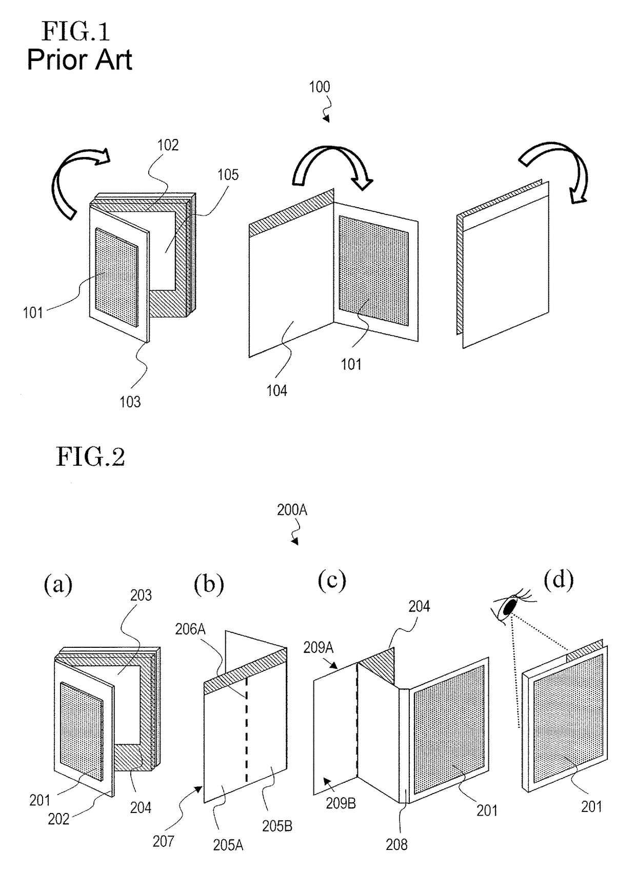
[0043]With reference to FIG. 2 to FIG. 5, the construction and functions of a case 200A for a mobile electronic device according to the present embodiment will be described.

[0044]FIG. 2 schematically shows external appearances of the case 200A for a mobile electronic device. In FIG. 2, (a) shows an external appearance of the case 200A in a state where a protection cover 202 thereof is open, as the case 200A is viewed from the front; (b) and (c) show external appearances of the case 200A in states where the protection cover 202 is open, as the case 200A is viewed from the back face; and (d) shows an external appearance of the case 200A in a state where the protection cover 202 is positioned at the back face, as the case 200A is viewed from the back face.

[0045]The case 200A for a mobile electronic device includes a solar cell module 201, the protection cover 202, a holder section 207, and a connecting portion 208. As shown in the figure, the case 200A for a mob...

second embodiment

[0065](Second Embodiment)

[0066]With reference to FIG. 6 and FIG. 7, the structure and functions of a case 200B for a mobile electronic device according to the second embodiment will be described.

[0067]The case 200B for a mobile electronic device according to the present embodiment differs from the case 200A for a mobile electronic device according to the first embodiment in that a valley-fold line 206B is provided in the connecting portion 208. Hereinafter, the differences will mainly be described, while omitting description of the similarities.

[0068]FIG. 6 schematically shows external appearances of the case 200B for a mobile electronic device. In FIG. 6, (a) is an external view of the case 200B in a state where the protection cover 202 is open, as the case 200B is viewed from the front; (b) and (c) are external views showing the case 200B in a state where the protection cover 202 is open, as the case 200B is viewed from the back face; and (d) is an external view of the case 200B i...

third embodiment

[0073](Third Embodiment)

[0074]With reference to FIG. 9 and FIG. 11, the structure and functions of a case 200C for a mobile electronic device according to the third embodiment will be described.

[0075]The case 200C for a mobile electronic device according to the present embodiment differs from the case 200A for a mobile electronic device according to the first embodiment in that it is a sliding type case. Hereinafter, the differences will mainly be described, while omitting description of the similarities.

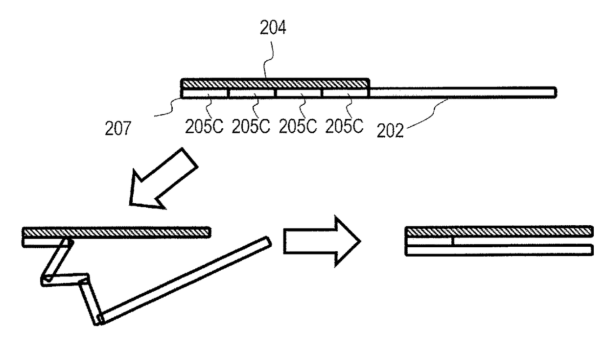
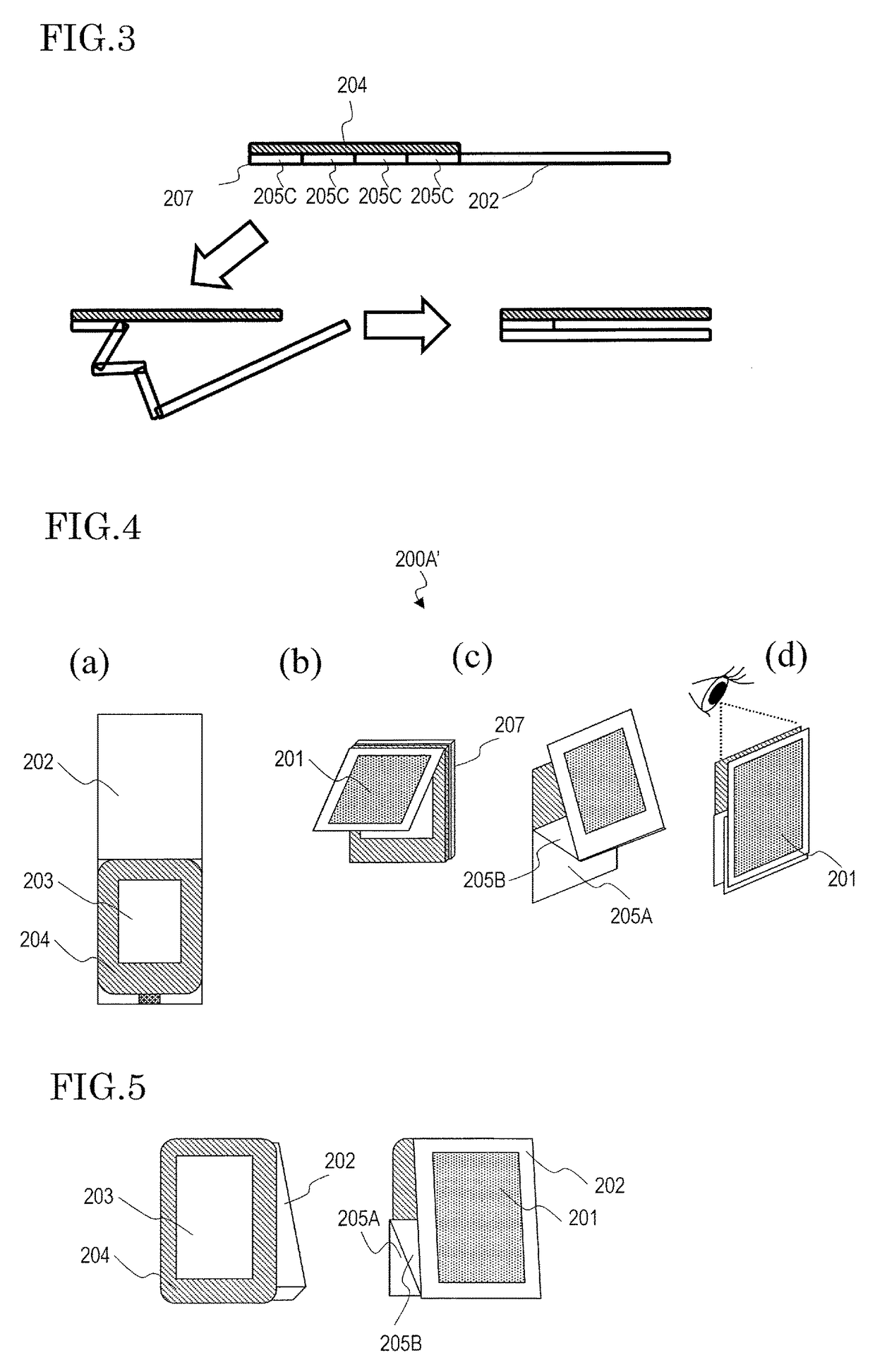
[0076]FIG. 9 schematically shows external appearances of the case 200C for a mobile electronic device. FIG. 9(a) shows an external appearance of the case 200C in a state where the protection cover 202 is in a protecting position, as the case 200C is viewed from the front. FIG. 9(b) shows an external appearance of the case 200C in a state where the protection cover 202 has slid from the protecting position, as the case 200C is viewed from the front. FIG. 9(c) shows an external appear...


PUM

PropertyMeasurementUnit
angleaaaaaaaaaa
angleaaaaaaaaaa
electric poweraaaaaaaaaa

Abstract

A case for a mobile electronic device is a case for a mobile electronic device which is capable of accommodating a mobile electronic device with a display surface, and supplying electric power to the mobile electronic device, the case including: a holder section having a first face which comes in contact with at least a portion of the mobile electronic device and a second face opposite from the first face; a protection cover to cover the display surface; a solar cell module provided on the protection cover to generate electric power, the solar cell module being externally exposed when the display surface is covered by the protection cover; and a moving mechanism capable of moving the protection cover over to the second face side while maintaining the solar cell module in an externally exposed state.

Description

BACKGROUND[0001]1. Technical Field[0002]The present invention relates to a case for a mobile electronic device, and more particularly to a case for a mobile electronic device such that the case includes a solar cell module. In the present specification, examples of mobile electronic devices include: mobile phones, smartphones, tablet PCs, calculators, portable game machines, music players, electronic book terminal devices, electronic dictionaries, electronic notebooks, and so on.[0003]2. Description of the Related Art[0004]As mobile electronic devices gain more prevalence, various cases and covers for mobile electronic devices are being developed. A case (or a cover) for a mobile electronic device aims to protect the mobile electronic device from impacts and prevent the display section and / or the main body thereof from becoming scratched, for example. Recently, cases or covers have been marketed which not only protect mobile electronic devices from impacts and scratches, but also ac...

Claims


Application Information

Patent Timeline
Patent Type & Authority Patents(United States)
IPC IPC(8): H04M1/00H04M1/18H02J7/35H04B1/3888H04M1/02H04B1/3883H01M10/46
CPCH02J7/355H04B1/3888H04M1/185H01M10/465H04B1/3883H04M1/0214H04M1/0222H02S20/30A45C11/00A45C15/00H02J7/35H04M1/0279A45C2011/003A45C2011/002Y02E10/50Y02E60/10
Inventor YAMANAKA, SHUNPEISHIBATA, SATOSHISHIBAHARA, MEHDI
Owner SHARP KK
Why Eureka
Try Eureka