Vaso-occlusive delivery device with kink resistant, flexible distal end

a delivery device and vasooocclusive technology, applied in the field of vasooocclusive delivery devices with flexible distal ends, can solve the problems of undeclared prolongation of the duration and risks of the procedure, exacerbate the problem, and susceptible to electrolysis of electrically severable junctions

Active Publication Date: 2017-05-02
STRYKER EURO OPERATIONS HLDG LLC +1
View PDF30 Cites 135 Cited by
  • Summary
  • Abstract
  • Description
  • Claims
  • Application Information

AI Technical Summary

Benefits of technology

[0012]In another aspect of the invention, a method of loading a vaso-occlusive coil on a delivery device includes providing a delivery device that includes an elongate core member having a severable junction and a hook disposed at a distal end thereof. One or more proximal windings of the vaso-occlusive coil are crimped. The hook is inserted into a lumen of the crimped portion of the vaso-occlusive coil. The hook is then rotated about the long axis of the elongate core member and the elongate core member is retracted proximally to secure the hook to the vaso-occlusive coil. An adhesive or epoxy may be used to aid in securely attaching the vaso-occlusive coil to the core member.

Problems solved by technology

An electrolytically severable junction is susceptible to electrolysis and, thus, disintegrates when the pusher wire is electrically charged in the presence of an ionic solution, such as blood or other bodily fluids.
The use of a stiff polymer jacket may also require the physician to relocate the catheter tip in the aneurysm during delivery of the occlusive device, or prior to placement of a further occlusive device, which undesirably extends the duration and risks of the procedure.
A relatively long pusher member junction can exacerbate the problem of conforming the vaso-occlusive coil and portion of the pusher member distal to the junction into the aneurysm.
If these components do not fit in the aneurysm, the catheter can be pushed back and move out of position, which can leave a tail of the coil in the parent artery, or present difficulties in repositioning the micro-catheter for subsequent coils to be delivered.

Method used


Image

  • Vaso-occlusive delivery device with kink resistant, flexible distal end
  • Vaso-occlusive delivery device with kink resistant, flexible distal end
  • Vaso-occlusive delivery device with kink resistant, flexible distal end

Examples


Embodiment Construction

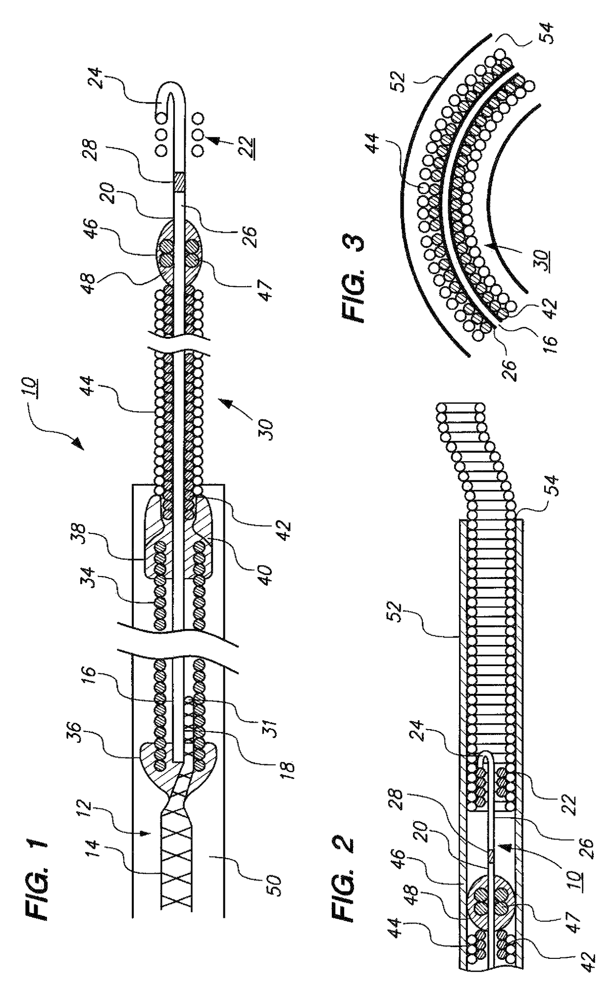
[0024]FIG. 1 illustrates an exemplary delivery system 10 according to one embodiment for the delivery of a vaso-occlusive device (not shown) to a vascular site in a human or veterinary patient includes an elongate pusher member 12 of conventional design and composition, except that, rather than comprising a unitary (single) wire member having a tapered distal end section, the pusher member 12 comprises a two-piece assembly, including a proximal pusher member 14 attached to a (lower profile) distal pusher member 16 at an attachment joint 18. It is believed that certain manufacturing advantages may be achieved by using a “two-piece” pusher member assembly, instead of a conventional unitary wire member. In particular, it is believed that the electrolytic detachment process may be more repeatable, and that manufacture of more uniform and consistent distal end dimensions may be achieved in a process using drawn wires having relatively small cross-sections that are attached to the main wi...


PUM


Abstract

A device for delivering an occlusive element includes an elongate sheath having a lumen therein. An elongate core member is disposed within the lumen and is formed from a proximal portion and distal portion connected via a joint. The distal portion of the elongate member includes a severable junction secured to the occlusive element. A marker coil is coaxially arranged around the distal portion of the elongate core member and is partially disposed inside the sheath lumen. A coil member is coaxially arranged around the distal portion of the elongate core member and coaxially arranged around at least a portion of the marker coil extending outside the lumen of the sheath. The coil member is secured at a distal end thereof to the distal portion of the elongate core member. The device resists axial compression while allowing for radial bending.

Description

REFERENCE TO RELATED APPLICATIONS[0001]This Application claims the benefit of U.S. Provisional Patent Application No. 60 / 690,570 filed on Jun. 14, 2005. U.S. Provisional Patent Application No. 60 / 682,562 is incorporated by reference as if set forth fully herein.FIELD OF THE INVENTION[0002]The field of the invention generally relates to systems and delivery devices for implanting vaso-occlusive devices for establishing an embolus or vascular occlusion in a vessel of a human or veterinary patient.BACKGROUND OF THE INVENTION[0003]Vaso-occlusive devices or implants are used for a wide variety of reasons, including treatment of intra-vascular aneurysms. A common vaso-occlusive device takes the form of a soft, helically wound coil formed by winding a platinum (or platinum alloy) wire strand about a primary mandrel. The relative stiffness of the coil will depend, among other things, on its composition, the diameter of the wire strand, the diameter of the primary mandrel, and the pitch of t...

Claims


Application Information

Patent Timeline
Patent Type & Authority Patents(United States)
IPC IPC(8): A61M29/00A61B17/12A61M25/09
CPCA61B17/12022A61B17/12154A61B17/12109A61B17/12113A61B2017/1205A61B2017/12054A61B2017/12063A61M25/09A61M2025/09133
Inventor HENRY, WILLIAM S.DALY, CHARLESFORD, RUSSELLWILLIAMS, MICHAEL D.DUONG, HANHDEVANEY, HUGHIERAMZIPOOR, KAMALTEOH, CLIFFORDMURPHY, RICHARDHUFFMASTER, ANDREWMCGILL, SCOTT
Owner STRYKER EURO OPERATIONS HLDG LLC
Why Eureka
Try Eureka