

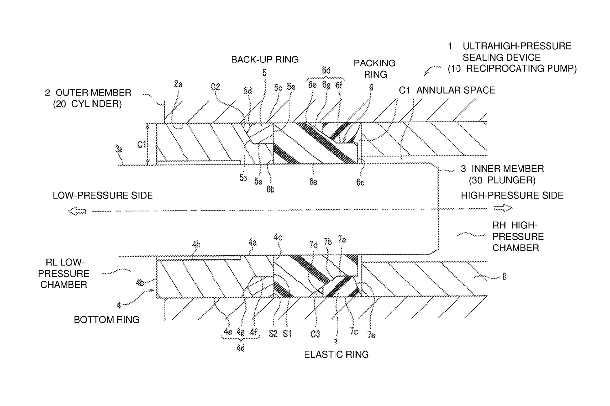
Ultrahigh-pressure sealing device and reciprocating pump
a sealing device and high-pressure technology, applied in the direction of machines/engines, liquid fuel engines, positive displacement liquid engines, etc., can solve the problems of shortening the lifetime of the seal, easy poor sealing of the back-up ring of the sealing device known in the art, etc., to improve the durability and improve the sealing performance.
- Summary
- Abstract
- Description
- Claims
- Application Information
AI Technical Summary
Benefits of technology
Problems solved by technology
Method used
Image

Examples
first modification
[0100]A first modification will now be described with reference to FIG. 4. The components that are the same as described in the above embodiments will be given the same reference numerals, and will not be described.
[0101]FIG. 4 is a schematic enlarged cross-sectional view of a main part of an ultrahigh-pressure sealing device according to the first modification.
[0102]As shown in FIG. 4, a packing ring 6A of the present modification includes a low-pressure-chamber beveled end 6Ab2. A back-up ring 5A also includes a high-pressure-chamber end 5Ae that is beveled. The low-pressure-chamber beveled end 6Ab2 is in contact with the high-pressure-chamber end 5Ae. A gap C4 is defined between the packing ring 6A and a bottom ring 4A. A low-pressure-chamber end 6Ab1 of the packing ring 6A and a high-pressures-side end 4Ac of the bottom ring 4A may be spaced from each other.
[0103]The packing ring 6A includes the low-pressure-chamber end 6Ab1 and the low-pressure-chamber beveled end 6Ab2 defining...
second modification
[0108]FIG. 5 is a schematic enlarged cross-sectional view of a main part of an ultrahigh-pressure sealing device according to a second modification.
[0109]As shown in FIG. 5, a packing ring 6B of the present modification includes a low-pressure-chamber end 6Bb that is beveled. A bottom ring 4B also includes a high-pressure-chamber end 4Bc that is beveled. The low-pressure-chamber end 6Bb and the high-pressure-chamber end 4Bc are in contact with each other. The back-up ring 5B has a gap-defining end face 5Bd, which extends perpendicular to the inner wall surface of the cylinder chamber 2a.
[0110]In this case, the low-pressure-chamber end 6Bb of the packing ring 6B increases its diameter from an outer peripheral surface of the plunger 30 to the inner wall surface of the cylinder chamber 2a toward the high-pressure chamber RH.
[0111]The high-pressure-chamber end 5Ae of the back-up ring 5B is in contact with the low-pressure-chamber end 6Bb. The high-pressure-chamber end 5Ae and the high-...
third modification
[0116]FIG. 6 is a schematic enlarged cross-sectional view of a main part of an ultrahigh-pressure sealing device according to a third modification.
[0117]As shown in FIG. 6, a back-up ring 5C of the present modification includes a low-pressure-chamber end 5Cf, which extends perpendicular to the inner wall surface of the cylinder chamber 2a from a low-pressure-chamber end of an inner periphery 5a.
[0118]This increases the area of the back-up ring 5C that comes in contact with the inner wall surface of the cylinder chamber 2a, and improves the sealing with the cylinder chamber 2a.
[0119]A high-pressure-chamber end 4c of the bottom ring 4C further includes a high-pressure-side inner peripheral end 4Cc1, a high-pressure-side middle end 4Cc2, and a high-pressure-side outer peripheral end 4Cc3. The high-pressure-side inner peripheral end 4Cc1 is in contact with the low-pressure-chamber end 6Ab1 of the packing ring 6A. The high-pressure-side middle end 4Cc2 is in contact with the low-pressu...
PUM
 Abstract
Description
Claims
Application Information