Adjustable photocontrol mounting assembly

a technology of mounting assembly and photocontrol, which is applied in the direction of lighting apparatus, lighting device details, lighting and heating apparatus, etc., can solve the problems of difficult to ensure that the weather seal is working properly, led light fixtures have very limited space inside their housings, etc., and achieve the effect of convenient manual rotation

Active Publication Date: 2017-05-02
IDEAL IND LIGHTING LLC
View PDF41 Cites 6 Cited by
  • Summary
  • Abstract
  • Description
  • Claims
  • Application Information

AI Technical Summary

Benefits of technology

[0015]The engagement portion may have a peripheral outer surface including gripping features thereon to facilitate manual rotation of the engagement portion of the receptacle about the peripheral region of the support member.

Problems solved by technology

Such operation requires certain disassembling of the receptacle and the challenge of not changing the desired receptacle orientation while re-tightening the screws.
However, lifting of the receptacle also disengages weather sealing that protect the fixture housing interior from the elements.
This presents a difficulty of ensuring that the weather seal is functioning properly to prevent water from entering the housing.
Therefore, LED light fixtures have very limited room inside their housings.

Method used


Image

  • Adjustable photocontrol mounting assembly
  • Adjustable photocontrol mounting assembly
  • Adjustable photocontrol mounting assembly

Examples


first embodiment

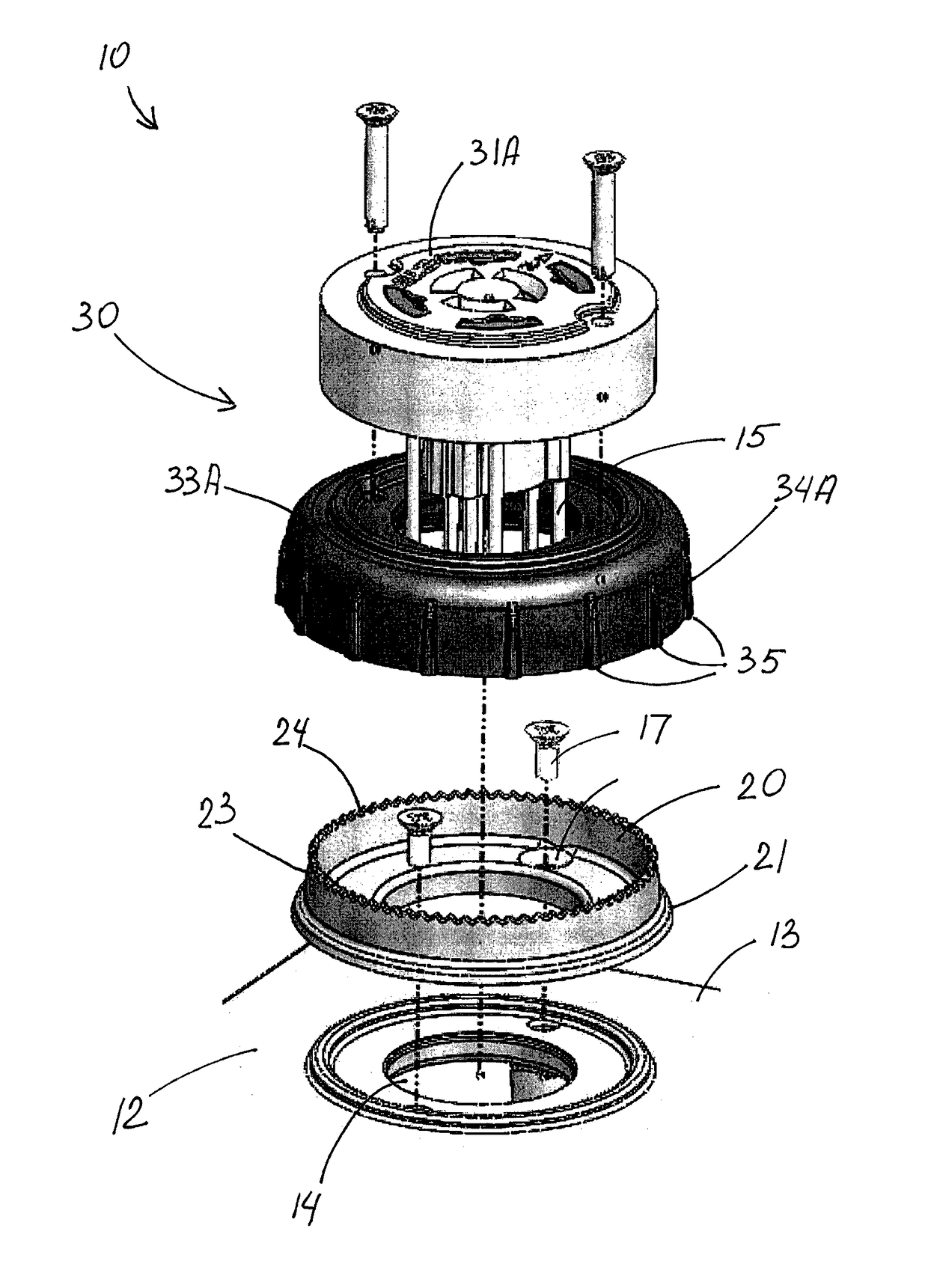
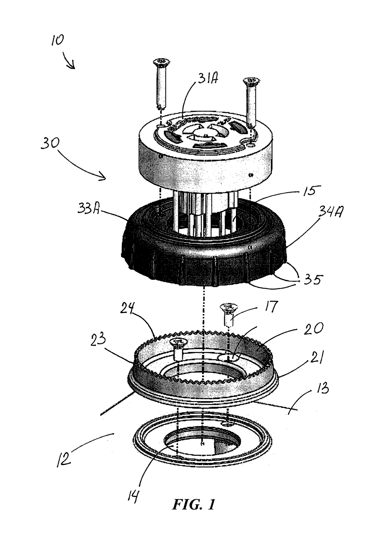
[0048]In a first embodiment shown in FIGS. 1-6, 9 and 10, engagement portion 33A has a peripheral outer surface 34A which includes gripping features 35 thereon to facilitate manual rotation of engagement portion 33A of receptacle 30A about peripheral region 21A of support member 20A.

[0049]FIGS. 3, 5, 6 and 8 show that peripheral region 21 of support member 20 includes a peripheral edge portion 22 spaced from exterior surface 13 of light-fixture housing 12. FIGS. 3A and 8A best show engagement portion 33 of receptacle 30 in snap-engagement with peripheral edge portion 22 of support member 20.

[0050]FIG. 1 best shows peripheral edge portion 22 of support member 20 as annular and unbroken. It should be understood that the peripheral edge portion of the support member may have an interrupted configuration. In some of such embodiments, the support member may include several spaced-apart pieces that together form such peripheral edge portion.

[0051]FIGS. 2 and 7 best show engagement portion...

second embodiment

[0059]In the second embodiment illustrated in FIGS. 7, 8 and 8A, receptacle body portion 31B and engagement portion 33B are formed as one-piece in rotational engagement with support member 20B.

[0060]FIGS. 1-10 illustrate also a method for connecting and holding a photocontrol with respect to a light fixture. FIG. 1 best shows the steps of providing support member 20 on exterior surface 13 of light-fixture housing 12 at opening 14 formed in housing 12. The step of positioning photocontrol receptacle 30 over support member 20 is best shown in FIGS. 1, 3-6 and 8. FIGS. 3, 3A, 8 and 8A show how photocontrol receptacle 30 is secured with respect to light-fixture housing 12. FIGS. 2-4 illustrate how secured receptacle 30 is rotated about support structure 20 for angular photocontrol adjustment on a light fixture.

[0061]The inventive method may also include the further step of connecting photocontrol 11 to receptacle 30 such that the rotating step may be after the connecting step, as seen i...


PUM

PropertyMeasurementUnit
rotationaaaaaaaaaa
resistanceaaaaaaaaaa
photoelectricaaaaaaaaaa

Abstract

An assembly for connecting and holding a photocontrol with respect to a light fixture. The assembly includes a support member and a photocontrol receptacle over and secured with respect to the support member. The support member is on an exterior surface of a light-fixture housing at an opening formed in the housing. The photocontrol receptacle is rotatable about the support member for angular photocontrol adjustment on the light fixture. The support member is fixed with respect to the exterior surface of the light-fixture housing. The receptacle has an engagement portion rotatably engaging the support member, thereby holding the receptacle with respect to the light-fixture housing while permitting rotation of the receptacle with respect thereto. Another aspect is a related method for connecting and holding a photocontrol with respect to a light fixture.

Description

FIELD OF THE INVENTION[0001]This invention relates generally to apparatus for connecting and holding photocontrols with respect to light fixtures, and to angular adjustment thereof.BACKGROUND OF THE INVENTION[0002]In the field of lighting, light fixtures are needed in many different settings, including high fixture positions for the most efficient use of light. Light fixtures for roadways, parking lots and other large outdoor areas typically use plug twist-lock photoelectric controllers (referred to herein as “photocontrols”) to automatically switch light fixtures on at dusk and off at dawn. These devices sense the intensity of the ambient light and switch the fixtures on and off accordingly. For best performance, photocontrols need to be oriented such that the cell faces in the direction of north in the northern hemisphere and south in the southern hemisphere, away from direct sunlight. It is desirable that photocell receptacles permit adjustment to the desired orientation.[0003]Fo...

Claims


Application Information

Patent Timeline
Patent Type & Authority Patents(United States)
IPC IPC(8): H01R4/50F21V23/04F21V17/02
CPCF21V23/0464F21V17/02Y10T29/49826
Inventor HOBSON, CHARLES O.
Owner IDEAL IND LIGHTING LLC
Why Eureka
Try Eureka