Method using near and far field ULF and ELF interferometry synthetic aperture radar for subsurface imaging

a synthetic aperture radar and near and far field technology, applied in the direction of measurement devices, instruments, electromagnetic wave detection, etc., can solve the problems of high cost, high cost, and difficulty in introducing power during fracturing operations, so as to reduce or eliminate the phase unwrapping error

Active Publication Date: 2017-05-02
DEEP IMAGING TECH INC
View PDF18 Cites 5 Cited by
  • Summary
  • Abstract
  • Description
  • Claims
  • Application Information

AI Technical Summary

Benefits of technology

[0020]Yet another object of the disclosed subject matter is to show that monitoring can occur throughout the operation and allow the user to immediately observe any possible problems as opposed to only operating before or after the fracturing operation occurs.
[0023]It is yet another object of the disclosed subject matter to achieve optimum results from real-world interferometric application by fine-tuning the specific engineering implementation to match the unique characteristics and challenges posed by the targets and the characteristics of the probing waves (e.g. positioning of the receivers; positioning the transmitter in more than one location; phase steering; phase focusing; etc, to overcome difficult geologies that might mask, shadow, or otherwise occult the area of interest).
[0024]It is an object of the disclosed subject matter to reduce or eliminate the phase unwrapping error due to the Doppler effect by having the disclosed subject matter remain stationary when readings are taken.
[0025]It is an object of the disclosed subject matter to regain the intrinsic advantage of moving the source and receivers over a target area by using multiple transmitter positions and using a technique of phase focusing.

Problems solved by technology

(d) There are intricate procedures required to move and relocate the sensor arrays for each sub-surface depth at which the fracturing operation that occurs.
In Cramer et al, the amount of power required will be significant and introducing this power during fracturing operations will be fraught with problems.
The power will directly control the depth of investigation and this may prove to be a limitation.
It is likely that without the critical step of tuning the antenna to the surrounding formation, the antenna will not couple reliably with the formation, resulting in inconsistent results and possible transmitter output stage failure, due to reflected signal from the formation.
Each of these systems is using distinct parts of the electromagnetic spectrum but none has been successfully applied to CSEM.
In fact, most practitioners of the art expect interference fringes to contain many multiples of pi phase shift across an image; however, as will be discussed further below, this is not the case with the disclosed subject matter.
One of the issues associated with this technique is the phase unwrapping error due to the Doppler effect, as disclosed in BASIC PRINCIPLES AND CURRENT ISSUES OF SAR INTERFEROMETRY by Olaf Hellwich, which is hereby incorporated by reference in its entirety.
Using short PRB codes severely limits the effective depth (e.g. less than 300 m).
There are several problems with current CSEM techniques that limit the ability to interpret the images created.
These problems occur because the current systems generate images with large spatial uncertainty.
Inevitably the method leads to imprecise and uncertain conclusions.

Method used


Image

  • Method using near and far field ULF and ELF interferometry synthetic aperture radar for subsurface imaging
  • Method using near and far field ULF and ELF interferometry synthetic aperture radar for subsurface imaging
  • Method using near and far field ULF and ELF interferometry synthetic aperture radar for subsurface imaging

Examples


second embodiment

[0095]In a second embodiment the interferometric system can use a technique of phase steering modified to produce phase focusing. The concept of phase steering is well understood in Radar Phase Array Antenna's. In the disclosed subject matter the phase steering is achieved by treating the receivers as transmitters and using the phase shifts between each to refer back to the object. This is also a well understood technique. The implication of using phase steering is that the invention must be capable of producing data from the receiver matrix that can be phase unwrapped or has a method for directly measuring phase.

[0096]Phase focusing is distinct from the process of phase steering in that instead of introducing the same phase shift for a receiver pair, a different phase shift for each is introduced such that the phase center for the receiver pair is adjusted toward a focal point.

[0097]Referring now to FIG. 4a. For a series of irregularly place receivers 405a, 405b and 405c on the sur...

third embodiment

[0100]A third embodiment uses a transmitted phase coherent PRB code designed to allow investigation of conductance and therefore phase velocity through the near field regime to intermediate field regime. Knowledge of the phase velocity in the upper strata will improve the likely hood of a unique solution to an image created through phase differences. Other codes are possible. The concept of near, intermediate and far field regimes within CSEM surveying can be understood by a person skilled in the art of CSEM surveying. The concept of a PRB code can be understood by a person skilled in the art of spread spectrum transmission schemes.

fourth embodiment

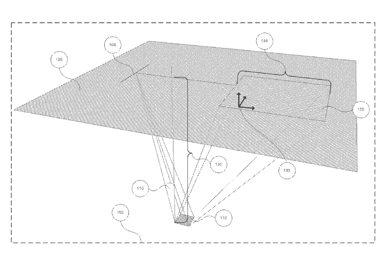
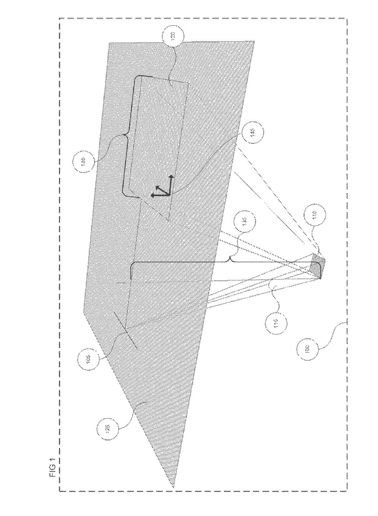
[0101]In one embodiment the depth information is collapsed to a single image plane, depicted in FIG. 1. A set of image planes are created at each conductive interface. Depth information can be recovered by using the Radar sounding timing technique of the

[0102]In a fourth embodiment, Radar sounding timing data can be found as follows: The transmitter transmits at a fixed rate with a transmit time synchronized to the GPS synchronizing clock. A plurality of receivers is also synchronized to the GPS synchronizing clock. By the framing method, a receiver is able to detect EM transit times from the transmitter to a responding formation and back to the receiver antenna. The transit time is defined as follows:

T=Dt→f / c*Vp+Td+Df→r / c*Vp

Where:[0103]T=transition time[0104]Dt→f=Distance from transmitter to target formation[0105]Df→r=Distance from target formation to receiver[0106]c=velocity of the EM signal in a vacuum[0107]Vp=Velocity of propagation of EM signal in the formation

Vp can be resolv...


PUM


Abstract

This invention relates to devices and processes for geophysical prospecting, subsurface fluid monitoring and, more particular, to the use of interferometric techniques using Control Source Electromagnetic (“CSEM”) and Magnetoturelic (“MT”) signals to create images of sub-surface structures and fluids.

Description

FIELD OF THE INVENTION[0001]The invention relates to devices and processes for geophysical prospecting, subsurface fluid monitoring and, more particularly, to the use of interferometric techniques using Control Source Electromagnetic (“CSEM”) and Magnetoturelic (“MT”) signals to create images of sub-surface structures and fluids.BACKGROUND OF THE INVENTION[0002]The current state of the art involves using processes that depend on listening devices, such as hydrophones, placed in an adjacent parallel well, or co-located around the well of interest. This method is commonly referred to as Micro Seismic Monitoring (MSM) and is typified by U.S. Pat. No. 7,872,944 and is incorporated herein by reference.[0003]The MSM technique has several basic flaws. (a) The method is a secondary indicator of the actual fluid location and extent within the sub-surface formation. (b) The method does not indicate if the proppant has been successfully introduced into the sub-surface formation. (c) The method...

Claims


Application Information

Patent Timeline
Patent Type & Authority Patents(United States)
IPC IPC(8): G01V3/12G01V3/38G01V3/08G01V3/00
CPCG01V3/12G01V3/083G01V3/38G01V2003/086G01S13/9023G01S13/885G01V3/36
Inventor SOKOLOWSKY, JAMESPAYTON, ROBERTPUGH, TREVORKALISH, ALEXANDERHICKEY, MARK
Owner DEEP IMAGING TECH INC
Why Eureka
Try Eureka