
Image forming apparatus that utilizes an adjustable alternately switching voltage

a technology of alternate switching voltage and forming apparatus, which is applied in the direction of electrographic process apparatus, instruments, optics, etc., can solve the problems of insufficient toner transfer and poor toner transfer to such embossed surfaces, and achieve the effect of increasing reducing the target value of vdc, and increasing the image area ratio of toner images to be printed

Active Publication Date: 2017-05-02
RICOH KK
View PDF33 Cites 1 Cited by
  • Summary
  • Abstract
  • Description
  • Claims
  • Application Information

AI Technical Summary

Benefits of technology

The patent describes an image forming apparatus that uses a transfer device to transfer toner onto a recording medium. The apparatus outputs an alternating voltage to the transfer device to move the toner image from the image bearer to the recording medium. The voltage alternates between a positive and negative polarity to transfer the image. The apparatus also adjusts the target value of the voltage to change the ratio of toner image to the overall image area. This helps to ensure the toner image is transferred without distortion or quality issues. The technical effect of this invention is to improve the image quality and accuracy of the printing process.

Problems solved by technology

More specifically, toner does not transfer well to such embossed surfaces, in particular, recessed portions of the surface.
This inadequate transfer of the toner appears as a pattern of light and dark in the resulting output image.

Method used


Image

  • Image forming apparatus that utilizes an adjustable alternately switching voltage
  • Image forming apparatus that utilizes an adjustable alternately switching voltage
  • Image forming apparatus that utilizes an adjustable alternately switching voltage

Examples


experiment 1

[0084]Next, a description is provided of the experiment using a waveform pattern in FIG. 5.

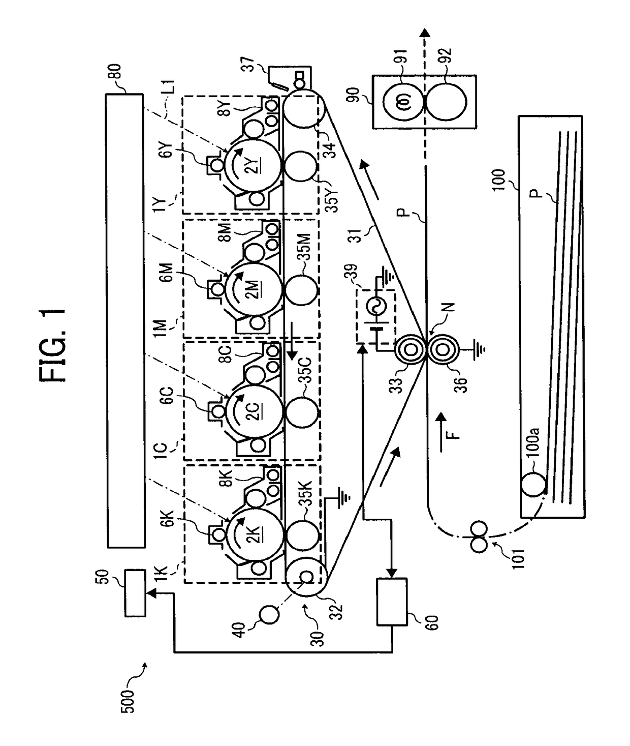
[0085]In this experiment, the structure of Imagio MP C7500 manufactured by RICO Company, Ltd. was employed. The secondary transfer bias (secondary transfer voltage) is applied to the image forming apparatus from a power source outside the apparatus without using a power source disposed therewithin. It should be noted that “Function Generator (FG 300)” manufactured by Yokogawa Electric Corporation is employed as the power source 39 of the secondary transfer bias to form a waveform of a superimposed voltage of the secondary transfer bias, which is then expanded by using “Model 10 / 40 High-Voltage Power Amplifier” manufactured by Trek, Inc. In addition, “LEATHAC 66” (a trade name, manufactured by TOKUSHU PAPER MFG. CO., LTD.) having a ream weight of 260 kg (a weight of 1000 sheets) and “LEATHAC 66” having a ream weight of 215 kg are used as a recording medium P to have a toner image transferred fr...

experiment 2

[0116]The following experiment was performed as well to analyze conditions to exhibit advantageous effects of the present embodiment.

[0117]In this experiment, “Imagio MPC 7500” manufactured by RICO Company, Ltd. employed in Experiment 1 was used as an image forming apparatus, and “LEATHAC 66” was used as a recording medium P. In Experiment 2, each of a solid image with an image area ratio of 100% and a line image with an image area ratio of 10% is transferred onto a recording medium with only the DC voltage applied. Then, the evaluations of the transferability were graded for the respective images. In addition, each of the solid image and the line image is also transferred onto a recording medium with the superimposed voltage applied, varying the level of the DC voltage included in the superimposed voltage. Then, the evaluations of the transferability were graded for the respective images as well. FIG. 14 is an illustration of evaluation results of Experiment 2. In FIG. 14, the soli...


PUM


Abstract

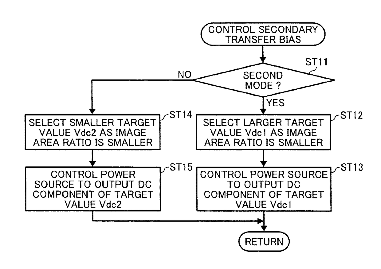
An image forming apparatus includes an image bearer, a transfer device, and a transfer bias power source. The transfer bias power source is configured to output an alternately switching voltage that alternates between a transfer-directional voltage having a polarity to transfer the toner image from the image bearer onto the recording medium and a return-directional voltage having an opposite polarity to the polarity of the transfer-directional voltage. The transfer bias power source is configured to reduce a target value of Vdc as an image area ratio of a toner image to be printed increases, and to increase the target value of Vdc as the image area ratio reduces, where Vdc is an average value of the alternately switching voltage during printing.

Description

CROSS-REFERENCE TO RELATED APPLICATION[0001]This patent application is based on and claims priority pursuant to 35 U.S.C. §119(a) to Japanese Patent Application No. 2015-034555, filed on Feb. 24, 2015, in the Japan Patent Office, the entire disclosure of which is hereby incorporated by reference herein.BACKGROUND[0002]Technical Field[0003]Aspects of the present disclosure relate to an image forming apparatus.[0004]Related Art[0005]An electrophotographic image forming apparatus conveys a transfer material to a transfer nip formed at a position opposing an image bearer and applies a transfer bias to transfer a toner image from the image bearer onto a recording medium in the transfer nip. In such a configuration, when using a recording medium having a coarse surface or an embossed surface such as Japanese paper (also known as Washi), a pattern of light and dark (unevenness of image density) according to the surface condition of the recording medium appears in an output image. More spec...

Claims


Application Information

Patent Timeline
Patent Type & Authority Patents(United States)
IPC IPC(8): G03G15/16
CPCG03G15/1665G03G15/161G03G15/1675
Inventor TANAKA, SHINYA
Owner RICOH KK
Learn More