Machine tool

a tool and tool mount technology, applied in the field of machine tools, can solve the problems of difficult replacement operation of the tool mount, large machine in the up and down direction, and large size of the machine in the up and down direction, and achieve the effect of improving the quality of the tool moun

Active Publication Date: 2017-05-09
DMG MORI CO LTD
View PDF14 Cites 2 Cited by
  • Summary
  • Abstract
  • Description
  • Claims
  • Application Information

AI Technical Summary

Benefits of technology

[0011]The disclosed embodiments of the present invention have been developed in view of the above-mentioned and / or other problems in the related art. The disclosed embodiments of the present invention can significantly improve upon existing methods and / or apparatuses.
[0012]The embodiments of the present invention has been made in view of the conventional circumstances, and aim to provide a machine tool in which the dimensions of the machine can be made more compact in the left and right direction and up and down direction, and the replacement operation of the tool mount is easy.
[0017]Also, since the tool mount is arranged on the operator side, when removing or attaching the tool mount from or to the tool mount installation portion to repair, replace, etc., the tool mount, the tool mount unlikely interferes with the spindle and therefore the replacement operation of the tool mount can be made easily. Further, since the tool mount is positioned closer to the operator, the so-called operator's accessibility to the tool mount is excellent, and the replacement operation, etc., of the edged tools mounted on the rotary member is easy.
[0018]Further, according to some embodiments as recited above, since the tool mount is arranged so that the axis of the rotary member is positioned below the axis of the spindle, the support stiffness of the tool mount can be easily secured and the replacement operation of the tool mount can be performed more easily.
[0019]According to some embodiments as recited above, since the indexing motor is arranged below the chip accommodation section, that is, more to the processing region side than the tool mount installation portion, the indexing motor can be prevented or controlled from protruding from the tool mount installation portion to the operator side, which in turn can make the operator's accessibility to the tool mount even better and make it easier to perform the replacement operation, etc., of the edged tools.
[0020]Further, since the indexing motor is covered by the chip accommodation section from above, although it is arranged within the processing region, it can prevent chips, cutting fluid, etc., from falling onto the motor without providing a dedicated cover, etc.

Problems solved by technology

In the conventional small-scale lathe described in the aforementioned Patent Document, since the tool mount is arranged on the upper or lower side of the spindle so as to overlap with the spindle, there was a problem that the dimension of the machine in the up and down direction became large.
Also, since the tool mount is arranged on the spindle side, there is also a problem that the replacement operation of the tool mount is difficult.
Thus, the problem that the replacement operation of the tool mount is difficult remains.

Method used


Image

  • Machine tool
  • Machine tool
  • Machine tool

Examples


embodiment 1

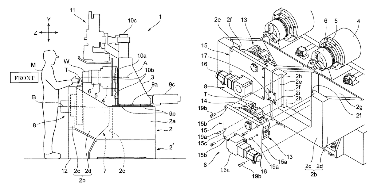
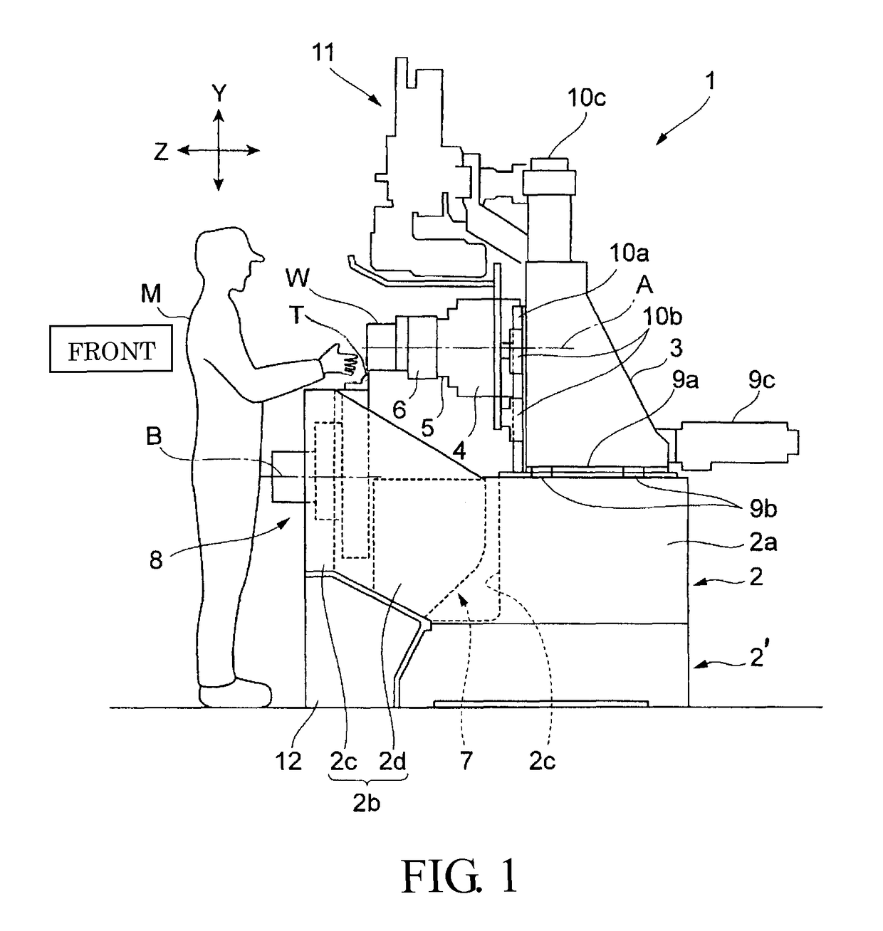
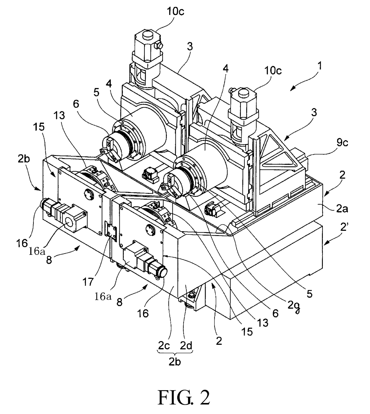
[0033]FIGS. 1 to 4 are drawings for explaining a lathe according to Embodiment 1 of the present invention. Further, in this embodiment, “front and back” respectively refers to a closer side and a farther side when seen from an operator M positioned at the front side of the machine, and “left and right” respectively refer to the left and the right side when seen from the operator M.

[0034]In the drawing, the reference symbol “1” is a type of lathe having spindles facing the operator M side. As best shown in FIG. 2, the lathe 1 is equipped with a pair of left and right beds 2 and 2, columns 3 and 3 arranged on base sections 2a and 2a of the beds 2 and 2 movably in the front and back direction (Z-axis direction as indicated in FIG. 1), spindle heads 4 and 4 movably supported on the front face of each column 3 in the up and down direction (Y-axis direction as indicated in FIG. 1), and tool mounts 8 and 8 arranged on the operator M side. The pair of beds 2 and 2 is mounted on a common bed...

embodiment 2

[0055]FIGS. 6 to 8 are drawings for explaining a lathe according to Embodiment 2 of the present invention. In the drawing, the same symbol as that in FIGS. 1 to 4 denotes the same or corresponding part.

[0056]In Embodiment 2, an indexing motor 26 is arranged below a chip accommodation section 27. The chip accommodation section 27 has a rectangular shape in a planar view surrounded by a bottom wall 27a, a rear side vertical wall 27b, vertical walls 27c and 27c on left and right sides, and a supporting plate 15, and is formed to extend from the below of the spindle 5 to the below of the turret 13.

[0057]The indexing motor 26 is set so that the main body section 26a is accommodated inside the motor accommodation section 2d formed below the bottom wall 27a of the chip accommodation section 27. Further, the flange part 26b is fastened and fixed by bolts to the attachment wall 2e of the motor accommodation section 2d.

[0058]A drive pulley 26d having meshing teeth is fixed to an output shaft...


PUM

PropertyMeasurementUnit
dimensionsaaaaaaaaaa
dimensionaaaaaaaaaa
stiffnessaaaaaaaaaa

Abstract

A machine tool includes a spindle equipped with a workpiece gripping portion arranged so as to face an operator side, the spindle being configured to rotatably drive a workpiece gripped by the workpiece gripping portion, and a tool mount equipped with a rotary member supporting a plurality of tools in a rotatably indexable manner about an axis parallel to an axis of the spindle. The tool mount is arranged at a tool mount installation portion formed to be positioned on the operator side in a manner such that the rotary member faces a workpiece gripping portion side.

Description

CROSS-REFERENCE TO RELATED APPLICATIONS[0001]The present application claims priority under 35 U.S.C. 119 to Japanese Patent Application No. 2014-073000, filed on Mar. 31, 2014 and Japanese Patent Application No. 2014-220281, filed on Oct. 29, 2014, the contents of which are incorporated herein by reference in its entirety.BACKGROUND OF THE INVENTION[0002]Field of the Invention[0003]The present disclosure relates to a machine tool equipped with a spindle for rotatably driving a workpiece and a tool mount having a plurality of edged tools, and more specially relates to an improvement of an arrangement structure of the spindle and the tool mount in which dimensions of the machine tool is made more compact in the left and right direction and the up and down direction.[0004]Description of the Related Art[0005]The following description of related art sets forth the inventors' knowledge of related art and certain problems therein and should not be construed as an admission of knowledge in ...

Claims


Application Information

Patent Timeline
Patent Type & Authority Patents(United States)
IPC IPC(8): B23B3/00B23B3/16B23B3/30B23Q37/00B23Q39/04B23Q39/00
CPCB23B3/161B23B3/30B23Q37/005B23Q39/04B23B2270/30B23Q2039/004Y10T82/2508B23B3/06B23B2270/00B23Q1/01
Inventor AKAI, TAKAYUKIMATSUMOTO, YOSHIHIROYAKOYAMA, MASASHITANAKA, TOSHIAKIFUKUMORI, MASAO
Owner DMG MORI CO LTD
Why Eureka
Try Eureka