Horizontal transverse sealing station

a transverse sealing and horizontal technology, applied in the direction of transportation and packaging, packaging, other domestic objects, etc., can solve the problems of high transport velocity of film tubes, and achieve the effect of long sealing time, low velocity and high velocity

Active Publication Date: 2017-05-16
SYNTEGON PACKAGING SYST AG
View PDF15 Cites 3 Cited by
  • Summary
  • Abstract
  • Description
  • Claims
  • Application Information

AI Technical Summary

Benefits of technology

[0004]In addition, a drive and / or control unit, which is designed to drive the transverse sealing unit in the displacement movement during the sealing process such that a velocity difference of the sealing movement and of the film tube in the transport direction is at least substantially compensated, is proposed. By a “drive and / or control unit” should be understood, in particular, a unit which is designed to trigger and / or to influence the displacement movement. The drive and / or control unit can have drives, such as gear and / or crank mechanisms, motors, in particular electric motors, as well as mechanical and / or electrical control devices. By a “compensation of a velocity difference of the sealing movement and the film tube in the transport direction” should in this context be understood, in particular, that the displacement movement is chosen such that the sealing surfaces and the film tube, at least while they are touching one another, have in the transport direction, at least substantially, a matching velocity. By “at least substantially” should be understood, in this context, a variance of less than 10%, preferably less than 5%, particularly preferably less than 1%. During the sealing process, the sealing surfaces can follow the film tube particularly well. A relative velocity between film tube and sealing surfaces can be avoided. A compression of the film tube and / or pulling on the film tube between the sealing surfaces can be avoided. Preferably, the drive and / or control unit can be designed to move the transverse sealing unit between two sealing processes counter to the transport direction back into a starting position and, for a next sealing process, to resynchronize the sealing surfaces with the film tube in the transport direction. The sealing surfaces can be moved, in a succession of sealing processes, synchronously with the film tube. Preferably, the velocity of the sealing movement of the sealing jaws during the sealing process can be set such that a desired sealing time is achieved. The sealing time can be defined, for example, by properties of the material of the film tube and / or requirements relating to the quality of the transverse sealing seams. Preferably, the displacement movement can compensate the remaining velocity difference between sealing movement and transport movement of the film tube. The sealing time can be set broadly independently of the velocity of the transport movement of the film tube. With a given sealing time, higher velocities of the film tube can be achieved. Limiting factors with respect to the setting of the sealing time can be, in particular, a possible deflection, acceleration and / or velocity of the displacement movement.
[0011]In addition, a horizontal tubular bag machine comprising a horizontal transverse sealing station is proposed. The horizontal tubular bag machine can have particularly long sealing times. A pack quality can be particularly high. Packaging materials which require high sealing times can be processed at high velocity. Alternatively, with the same sealing time, higher velocities can be achieved.

Problems solved by technology

Transport velocities of the film tube can be particularly high.

Method used


Image

  • Horizontal transverse sealing station
  • Horizontal transverse sealing station
  • Horizontal transverse sealing station

Examples


Embodiment Construction

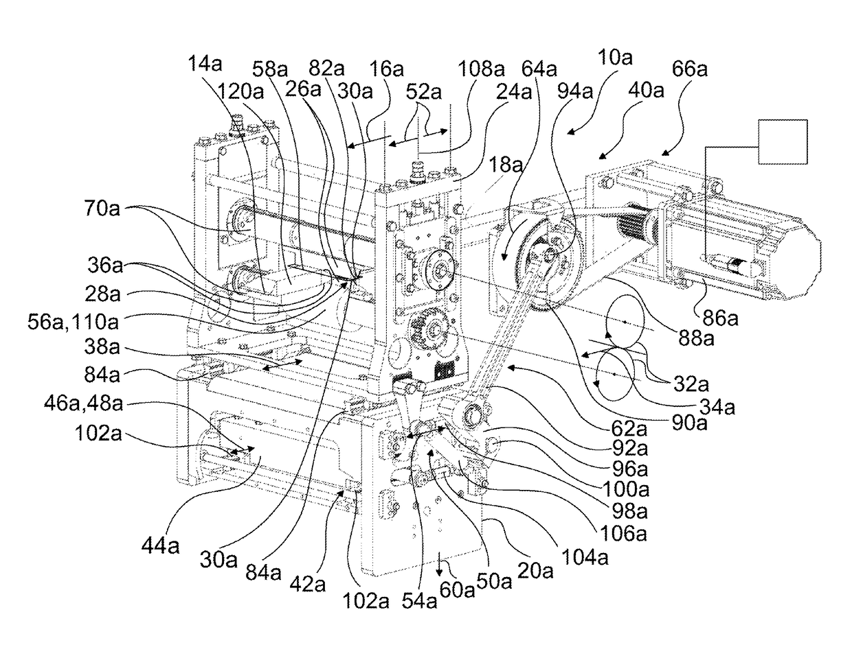
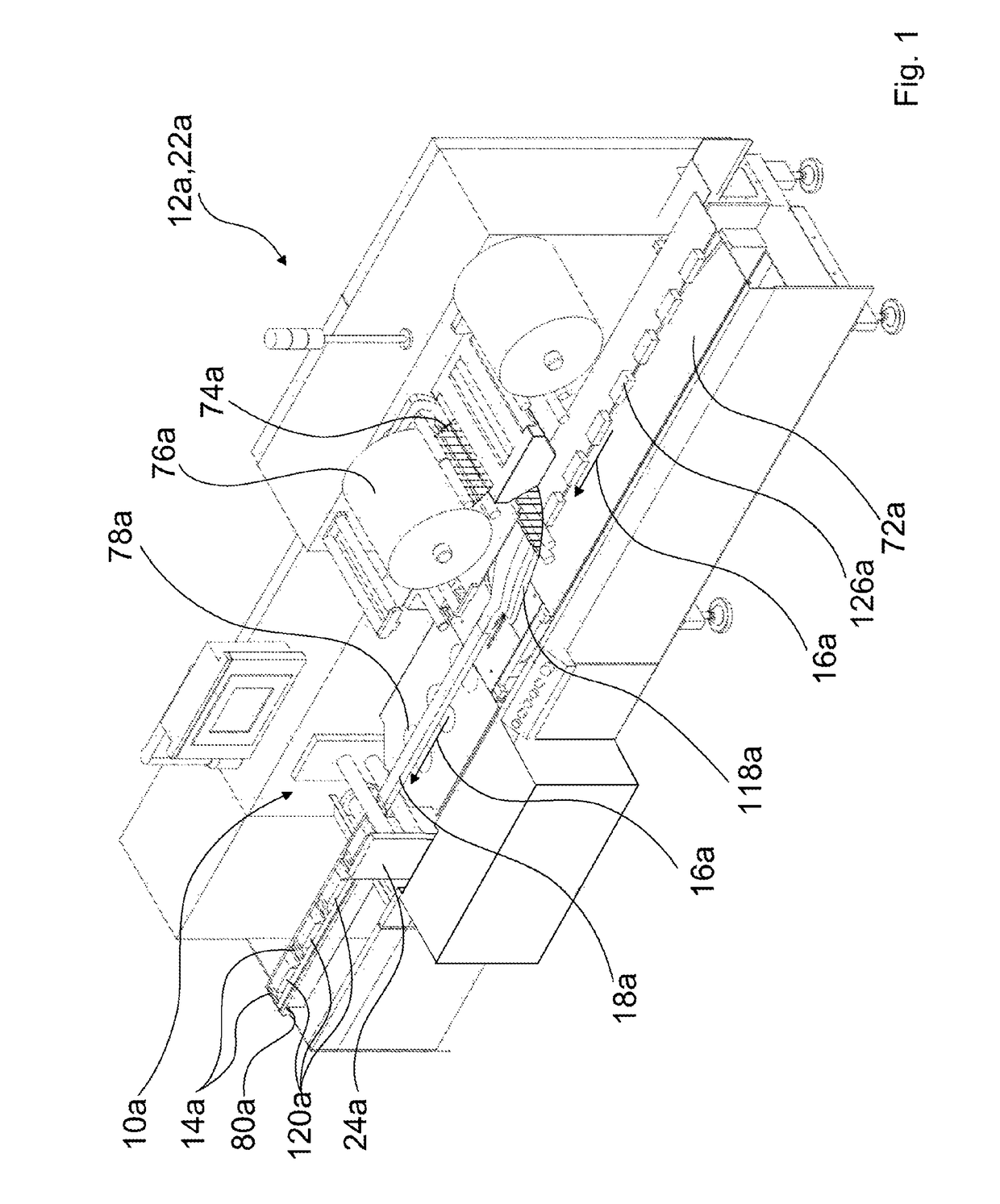
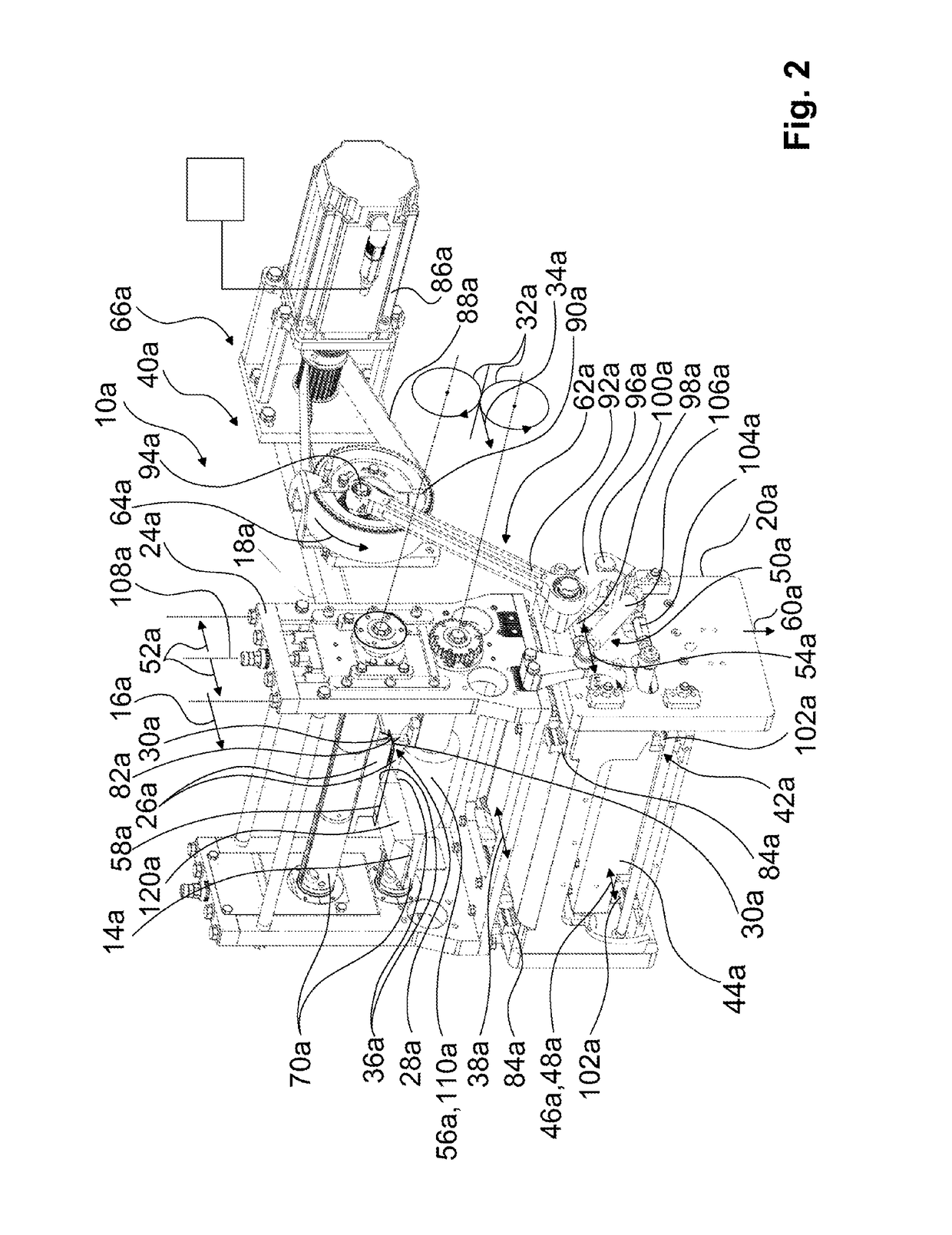
[0017]FIG. 1 shows a packaging machine 22a configured as a horizontal tubular bag machine 12a and comprising a horizontal transverse sealing station 10a. Products to be packed 126a are guided in single track on a feed tray 72a in a horizontal transport direction 16a, by means of dogs (not represented in detail here) of a feed chain, to the horizontal transverse sealing station 10a. A material web 74a is unrolled from a packaging material roller 76a and formed with the aid of a forming shoulder 118a (not indicated here), around the products to be packed 126a, into a film tube 18a. The film tube 18a is transported continuously in the horizontal transport direction 16a and sealed below the products 126a by a horizontal longitudinal sealing unit 78a along a longitudinal sealing seam. Subsequently, the horizontal transverse sealing station 10a seals the film tube 18a along transverse sealing seams 14a and thus forms sealed packs 120a containing the products 126a. The horizontal transvers...


PUM

PropertyMeasurementUnit
movementaaaaaaaaaa
pressureaaaaaaaaaa
displacement movementaaaaaaaaaa

Abstract

The invention relates to a horizontal transverse sealing station (10a-b), in particular for a horizontal tubular bag machine (12a-b), for producing transverse sealing seams (14a-b) on at least one film tube (18a-b) transported in a continuous, at least essentially horizontal transport direction (16a-b), comprising a transverse sealing station base (20a-b) fixedly connected to a packing machine (22a-b), a transverse sealing unit (24a-b), and at least one sealing jaw pair (28a-b) movably mounted on the transverse sealing unit (24a-b) and formed by two sealing jaws (26a-b), the sealing surfaces (30a-b) of which come closer to each other during a sealing process in a sealing movement (32a-b), which relative to the transverse sealing unit (24a-b) is provided with at least one movement component (34a-b) in the transport direction (16a-b), in order to seal material layers (36a-b) of the film tube (18a-b) between the sealing surfaces (30a-b) by way of heating and / or applying pressure, and to remove again at the end of the sealing process. According to the invention the transverse sealing unit (24a-b) is driveably mounted on the transverse sealing station base (20a-b) in a displacement movement (38a-b) that is at least substantially parallel to the transport direction (16a-b).

Description

BACKGROUND OF THE INVENTION[0001]A horizontal transverse sealing station for a horizontal tubular bag machine, for producing transverse sealing seams on at least one film tube transported in a continuous, at least substantially horizontal transport direction, comprising a transverse sealing station base, which is fixedly connected to the tubular bag machine, comprising a transverse sealing unit, and comprising at least one sealing jaw pair, which is movably mounted on the transverse sealing unit and is formed by two sealing jaws and the sealing surfaces of which, during a sealing process, come closer together in a sealing movement having relative to the transverse sealing unit at least one movement component in the transport direction, in order to seal material layers of the film tube between the sealing surfaces, under the application of heat and / or pressure, and to move said material surfaces apart again at the end of the sealing process, has already been proposed.SUMMARY OF THE I...

Claims


Application Information

Patent Timeline
Patent Type & Authority Patents(United States)
IPC IPC(8): B32B37/00B29C65/00B29C65/18B29C65/48B29C65/78B29C65/08B65B9/067B65B51/30B29C65/30B29L23/00B29L31/00
CPCB29C66/83543B65B9/067B65B51/306B29C66/849B29C65/08B29C65/18B29C65/4825B29C65/7894B29C66/81465B29C66/83513B29C66/1122B29C66/133B29C66/4312B29C66/4322B29C65/087B29C65/305B29C66/723B29C66/83413B29C66/86533B29L2023/00B29L2031/7128B29C65/745B29C66/8223B29C66/8225B29C66/8246B29C66/8412B29C66/93451
Inventor THAERIGEN, JAN
Owner SYNTEGON PACKAGING SYST AG
Why Eureka
Try Eureka