Brake pad apparatus

a brake pad and apparatus technology, applied in the direction of noise/vibration control, axially engaging brake components, braking elements, etc., can solve the problems of large amount of brake fluid consumption, higher drag torque on the brake assembly, etc., to improve fuel economy and brake pedal feel, and reduce brake drag and fluid consumption.

Active Publication Date: 2017-05-16
BWI (SHANGHAI) CO LTD
View PDF25 Cites 2 Cited by
  • Summary
  • Abstract
  • Description
  • Claims
  • Application Information

AI Technical Summary

Benefits of technology

[0008]An improved brake pad apparatus is provided for engaging a rotor of a brake assembly of a vehicle to reduce the speed of the vehicle. The brake pad apparatus includes a backing plate that has an inside surface and an outside surface. A liner is connected to the inside surface of the backing plate for contacting the rotor for creating a frictional force against the rotor to reduce the speed of the vehicle. An insulating layer is connected to the outside surface of the backing plate for providing heat and noise insulation to the backing plate during contact of the liner against the rotor. At least one projection extends from the outside surface of the backing plate through the insulating layer and past the insulating layer to an engagement surface for being engaged by a pressing member of the brake assembly while preventing the pressing member from engaging the insulating member.
[0010]The invention in its broadest aspect therefore circumvents the issues of the insulating layer being constrained by the pressing member by providing for direct contact between the projections and the pressing member. Therefore, the damping properties of the insulating layer remain active over the backing plate while the issues associated with clamping thereof are alleviated. Accordingly, improvements in both brake drag reduction and fluid consumption are provided to the brake assembly, which consequently also provides improved fuel economy and brake pedal feel.

Problems solved by technology

Along with the positive insulative characteristics that are provided by the insulating layer, it has also been recognized that as a result of the pressing member directly engaging the insulating layer, the brake assembly may be subjected to higher drag torque and larger amounts of brake fluid consumption (displacement).

Method used


Image

  • Brake pad apparatus
  • Brake pad apparatus
  • Brake pad apparatus

Examples


Embodiment Construction

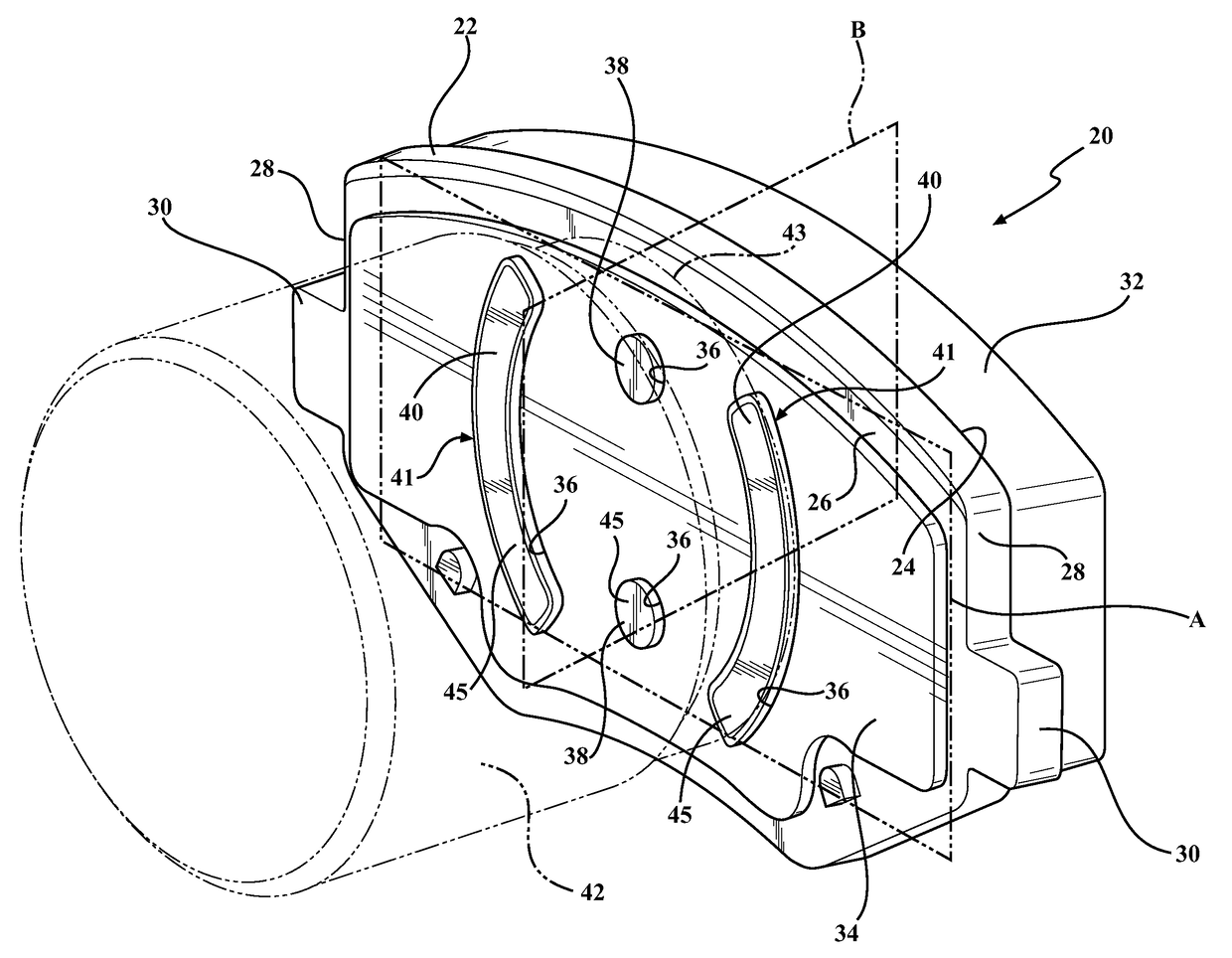
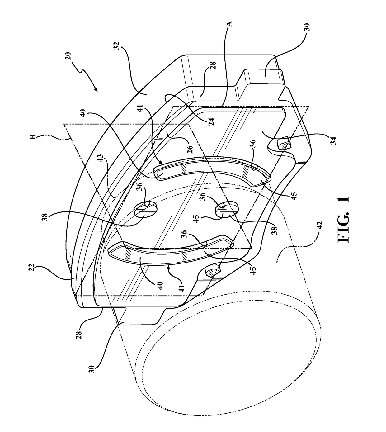
[0019]Referring to the Figures, wherein like numerals indicate corresponding parts throughout the several views, a brake pad apparatus 20, 120, 220, 320 is generally shown for engaging a rotor of a brake assembly of a vehicle for reducing the speed of the vehicle. It should be appreciated that the subject brake pad apparatus 20, 120, 220, 320 could be utilized on various vehicles including, but not limited to, automobiles and motorcycles.

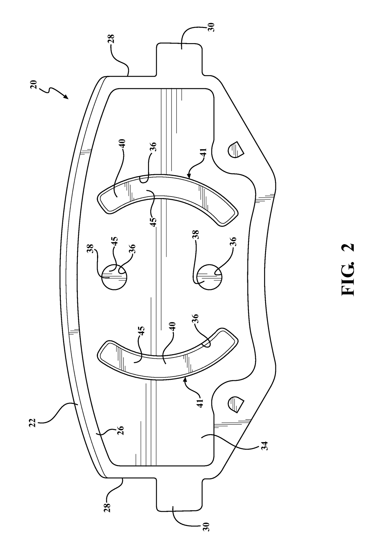
[0020]As best shown in FIG. 1, the brake pad apparatus 20, 120, 220, 320 includes a backing plate 22 made of a steel material that extends along a first plane A. The backing plate 22 has an inside surface 24 and an outside surface 26, and extends between a pair of sides 28. It should be appreciated that the backing plate 22 could be made of other materials such as, but not limited to, other metals or organic polymer materials.

[0021]A pair of tabs 30 each extend from one of the sides 28 of the backing plate 22 for being received by a mounting bracket...


PUM


Abstract

The invention provides for a brake pad apparatus for connecting to a brake assembly of a motor vehicle. The brake pad apparatus includes a backing plate that extends along a first plane and has an inside surface and an outside surface. A liner is connected to the inside surface of the backing plate for contacting the rotor for creating a frictional force against the rotor to slow the motor vehicle. An insulating layer is connected to the outside surface of the backing plate for providing heat and noise insulation during contact of the liner against the rotor. At least one projection extends from the outside surface of the backing plate through the insulating layer, and past the insulating layer for being engaged by a pressing member of the brake assembly for compressing the liner against the rotor of the brake assembly.

Description

CROSS REFERENCE TO RELATED APPLICATIONS[0001]This U.S. patent application Ser. No. claims the benefit of U.S. Provisional Patent Application Ser. No. 62 / 118,182 filed on Feb. 19, 2015 entitled “BRAKE PAD APPARATUS,” the entire disclosure of the application being considered part of the disclosure of this application and hereby incorporated by reference.BACKGROUND OF THE INVENTION[0002]1. Field of the Invention[0003]A brake pad apparatus. More particularly, a brake pad apparatus including at least one projection extending past an insulating layer of the brake pad apparatus for being engaged by a pressing member of a brake assembly.[0004]2. Description of the Prior Art[0005]Conventional disc brake assemblies for vehicles generally include a pair of brake pads which are disposed on opposing sides of a brake rotor and are drawn against the rotor to create a frictional clamp force, which in turn slows the vehicle. The frictional clamp force is typically generated by way of at least one hy...

Claims


Application Information

Patent Timeline
Patent Type & Authority Patents(United States)
IPC IPC(8): F16D65/00F16D65/092F16D55/00
CPCF16D65/0006F16D65/092F16D2055/0029F16D65/005
Inventor HOXIE, STEVEN GLENNMYERS, WILLIAM
Owner BWI (SHANGHAI) CO LTD
Why Eureka
Try Eureka