Supercharge Your Innovation With Domain-Expert AI Agents!

Signal control circuit and switching apparatus for increased current control

a signal control circuit and switching apparatus technology, applied in the direction of dc-dc conversion, power conversion systems, instruments, etc., can solve the problems of reducing the accuracy of a current control loop, and achieve the effect of increasing the accuracy of current programmed control

Active Publication Date: 2017-05-16
SILICON WORKS CO LTD
View PDF14 Cites 1 Cited by
  • Summary
  • Abstract
  • Description
  • Claims
  • Application Information

AI Technical Summary

Benefits of technology

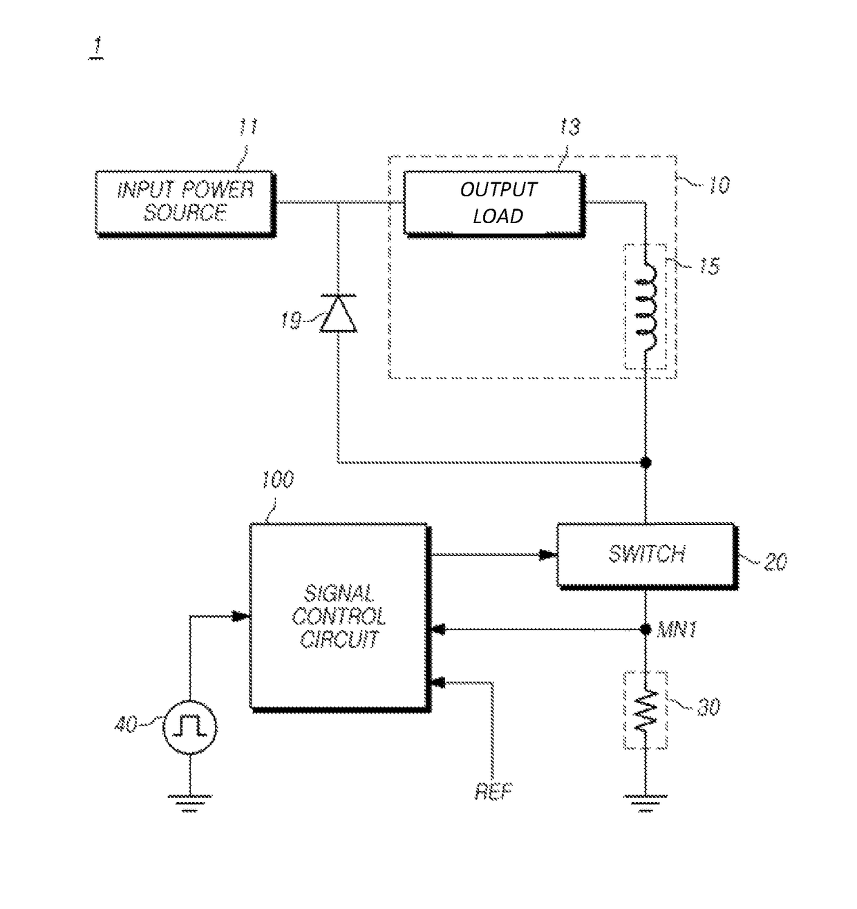
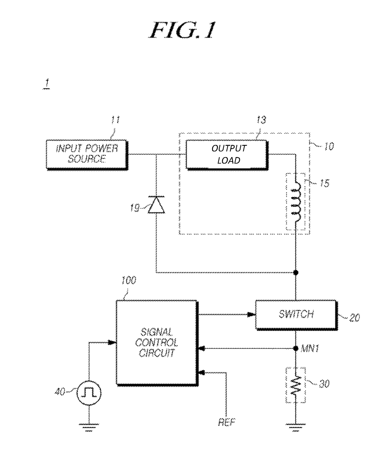
The technical problem this patent aims to solve is to provide a switching apparatus that improves the accuracy of current programmed control, as well as a signal control circuit that achieves the same.

Problems solved by technology

Such a peak current control scheme may have a fast transient response and stability, but may cause a switching ripple current of an inductor to reduce the accuracy of a current control loop.

Method used


Image

  • Signal control circuit and switching apparatus for increased current control
  • Signal control circuit and switching apparatus for increased current control
  • Signal control circuit and switching apparatus for increased current control

Examples


Embodiment Construction

[0032]The advantages and features of the present disclosure and methods of achieving the same will be apparent by referring to embodiments of the present disclosure as described below in detail in conjunction with the accompanying drawings. However, the present disclosure is not limited to the embodiments set forth below, but may be implemented in various different forms. The following embodiments are provided only to completely disclose the present invention and inform those skilled in the art of the scope of the present disclosure, and the present invention is defined only by the scope of the appended claims. Throughout the specification, the same or like reference numerals designate the same or like elements.

[0033]When an element is referred to as being “connected to” or “coupled to” any other element, not only the element may be directly connected or coupled to the other element, but also another new element may be interposed between them. Contrarily, when an element is referred...


PUM


Abstract

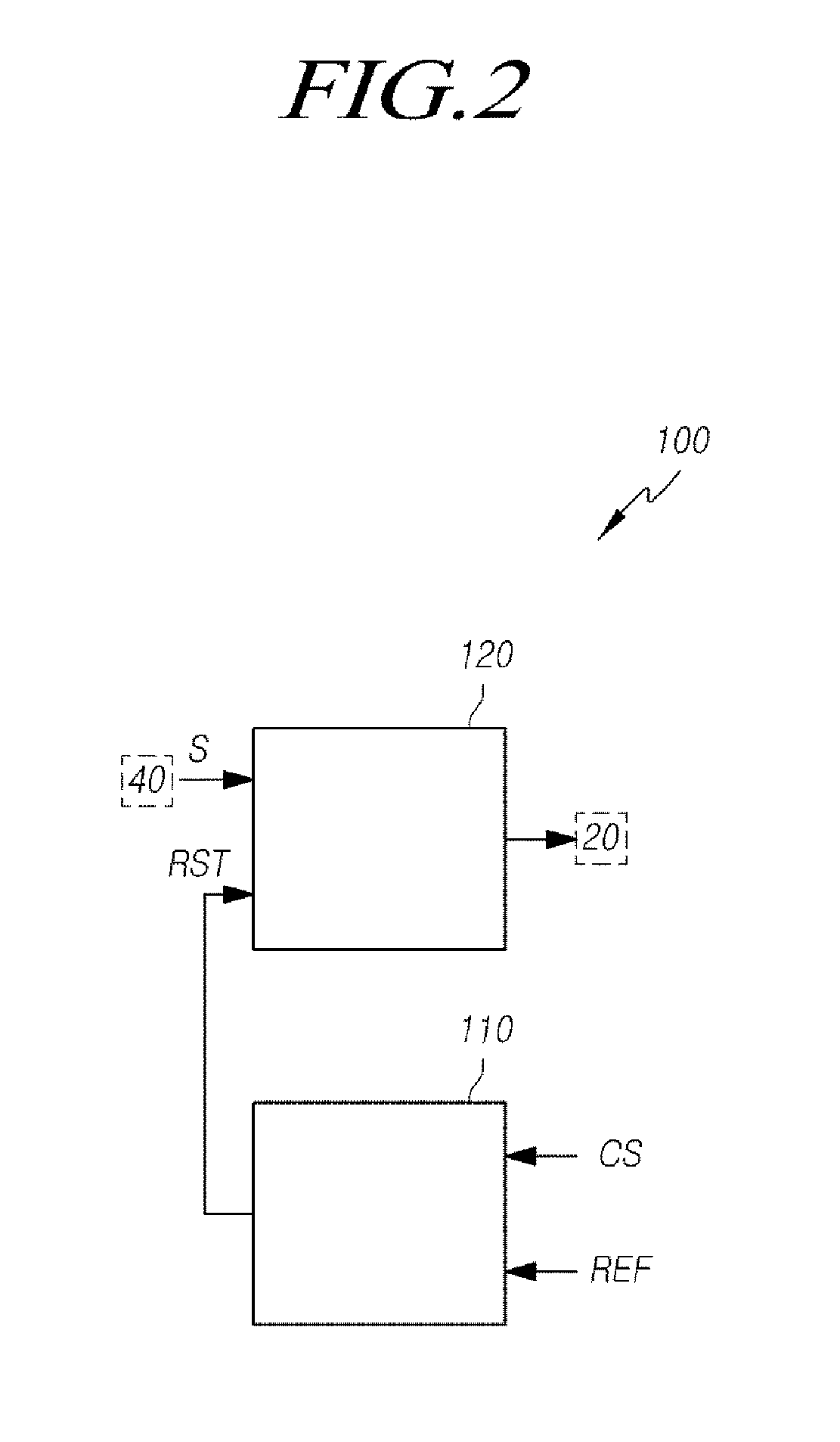
A signal control circuit and a switching apparatus are provided. The switching apparatus includes: a switch for controlling a current flowing through an inductive element; a monitoring node connected with the switch; and a signal control circuit, connected with the monitoring node and a reference voltage, for turning on / off the switch, wherein the signal control circuit includes an integrator for generating a comparison voltage by using a monitoring voltage of the monitoring node and the reference voltage, wherein the integrator includes: a resistor unit; a capacitor unit; and an auto-calibrator for receiving at least one selection signal and determining at least one of a resistance of the resistor unit and a capacitance of the capacitor unit, during a power-up period, and allowing a peak value of the comparison voltage to fall within a target range.

Description

CROSS-REFERENCE TO RELATED APPLICATIONS[0001]This application claims priority from and the benefit under 35 U.S.C. §119(a) of Korean Patent Application No. 10-2014-0061009, filed on May 21, 2014, which is hereby incorporated by reference for all purposes as if fully set forth herein.BACKGROUND[0002]1. Field of Technology[0003]The present disclosure relates to a signal control circuit and a switching apparatus.[0004]2. Description of the Prior Art[0005]The current programmed control of the related art mainly uses a peak current of a switching transistor. Such a peak current control scheme may have a fast transient response and stability, but may cause a switching ripple current of an inductor to reduce the accuracy of a current control loop. Accordingly, the peak current control has a limit in sensing an accurate average current, and needs to sense all current flowing through the inductor in order to sense the accurate average current. Reference is made to U.S. Pat. No. 7,863,836.SUM...

Claims


Application Information

Patent Timeline
Patent Type & Authority Patents(United States)
IPC IPC(8): H02M3/156H02M3/335G05F1/44
CPCH02M3/156G05F1/44H02M3/33507
Inventor KWON, OK HWANLIM, BAEK MINJIN, HAI FENGHONG, JU PYOKIM, SUNG HWANLEE, JU HYUNMOK, JIN WONKIM, JU YEONG
Owner SILICON WORKS CO LTD
Features
  • R&D
  • Intellectual Property
  • Life Sciences
  • Materials
  • Tech Scout
  • Unparalleled Data Quality
  • Higher Quality Content
  • 60% Fewer Hallucinations
Learn More