
Device for defining a cutting plane for a bone resection

a cutting plane and bone resection technology, applied in the field of bone resection cutting plane devices, can solve the problems of difficult to keep such foot clamps stable, difficult to tightly secure the foot clamps, and device disclosed

Active Publication Date: 2017-05-23
WALDEMAR LINK GMBH & CO
View PDF15 Cites 6 Cited by
  • Summary
  • Abstract
  • Description
  • Claims
  • Application Information

AI Technical Summary

Benefits of technology

The invention is a device for bone resection that includes a base body and a cut-guiding body. The cut-guiding body can be tilted relative to the base body to adjust the position of the cutting plane. The tilt mechanism is easy to operate and reliable in maintaining the desired position. The device is designed for repeated use and can be easily cleaned and sterilized. The cut-guiding body is releasably and removably disposed on the linear guide for easy separation for cleaning and sterilization. The guide and slide are designed with a spring force to securely hold the slide in place, eliminating the need for additional spring elements and reducing manufacturing costs. The device can be easily adjusted to different angles and can be connected to an extramedullary aligning rod or an intramedullary reference for flexibility in alignment.

Problems solved by technology

It is usually quite difficult to tightly secure the foot clamp there because excessively high retaining forces cannot be applied, so as not to endanger the blood supply to the foot.
Accordingly, it is often not easy to keep such foot clamps stable and thus also, by making an adjustment in this area, to make a corresponding, accurate and precision adjustment of the angular position.
However, the device disclosed in this document is comparatively user-unfriendly, in particular with regard to the adjustment of the tilt(s) of the cutting plane(s) with respect to the slope angle and / or the varus / valgus angle.
In addition, screws are used to secure the angular positions of the cutting plane, but such screws can become loosened, in particular when vibrations occur, such as vibrations generated by a cutting tool used to perform the bone resection and transmitted to the cut-guiding element by means of the cut-guiding slot provided as a cut-guiding structure.
There is therefore the risk of a faulty adjustment and / or displacement of the preset cutting plane during the resection cutting, so that a repeat resection becomes necessary in the worst case.

Method used


Image

  • Device for defining a cutting plane for a bone resection
  • Device for defining a cutting plane for a bone resection
  • Device for defining a cutting plane for a bone resection

Examples


Embodiment Construction

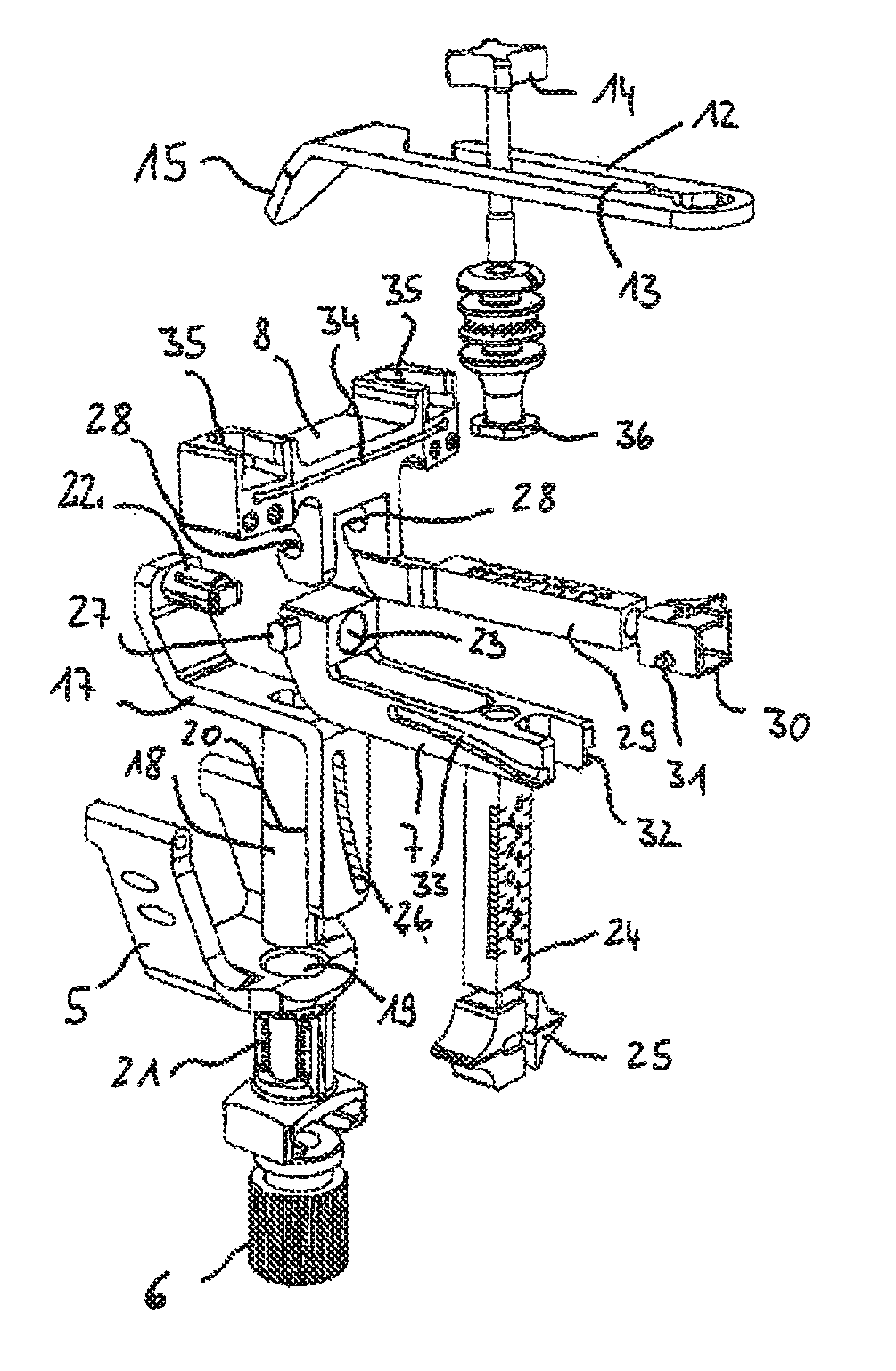
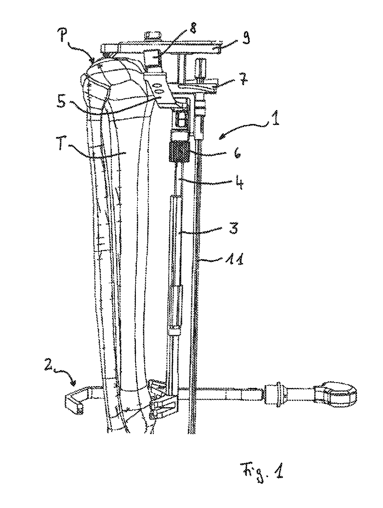
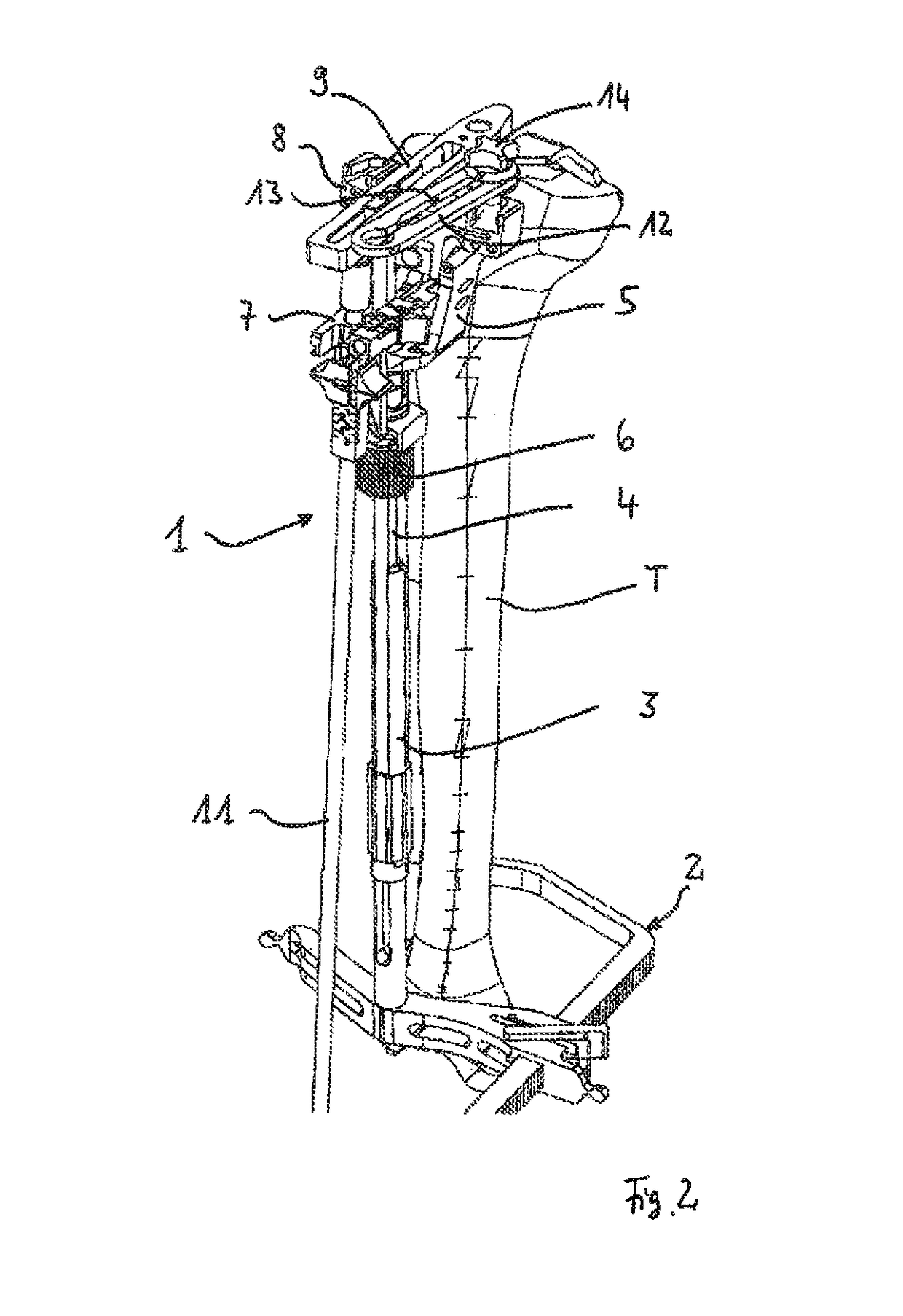
[0007]A remedy is to be created here with this invention by refining a device of the type described in the introduction in that the device includes a base body that can be positioned on the bone as well as a cut-guiding body which can be attached to the base body in a variable position and has a cut-guiding structure for guiding a cutting tool in the cutting plane, where the cut-guiding body can be tilted relative to the base body by means of a first adjustable tilt mechanism about at least one axis for an angle adjustment of the cutting plane; and wherein the extent that the tilt mechanism is simple to operate and is reliable with regard to the accuracy of the position of the cutting plane, once its position has been set, even while performing the resection cut.

[0008]A solution to this problem is offered with the present invention through a device having the features a base body that can be positioned on the bone as well as a cut-guiding body which can be attached to the base body ...


PUM


Abstract

An adjustable device for defining a cutting plane for bone resection comprising a base positionable on the bone and a cut-guiding element placeable on the base. The cut-guiding element includes a cut-guiding structure for guiding a cutting tool in the cutting plane, the cut-guiding element being tiltable relative to the base about at least one first axis by an adjustable tilt mechanism to adjust the angle of the cutting plane. The tilt mechanism includes a rectilinear guide and a slide that is linearly displaceable along the guide in the longitudinal direction. The tilt mechanism includes a guide portion relative to which an effective portion of the slide is displaced; the guide portion and the effective portion having interacting structures forming a sliding guide effective at a right angle to the longitudinal direction.

Description

TECHNICAL FIELD[0001]The present invention relates to a device for defining a cutting plane for bone resection which includes a base body that can be positioned on the bone as well as a cut-guiding body which can be attached to the base body in a variable position and has a cut-guiding structure for guiding a cutting tool in the cutting plane, where the cut-guiding body can be tilted relative to the base body by means of a first adjustable tilt mechanism about at least one axis for an angle adjustment of the cutting plane.PRIOR ART[0002]In medicine, in particular for the use of joint endoprostheses in orthopedic surgery, resection cuts are made to remove the worn regions of the bones involved in the respective joint and to create a defined binding geometry for the joint endoprosthesis parts to be used. It is important for the resection cuts to be guided precisely, so that an endoprosthetic replacement will permit optimal function with regard to the geometry in which it is positioned...

Claims


Application Information

Patent Timeline
Patent Type & Authority Patents(United States)
IPC IPC(8): A61B17/15A61B17/17A61F2/46A61B90/00
CPCA61B17/1764A61B17/155A61B17/157A61B2090/067A61F2002/4668
Inventor DMUSCHEWSKY, KLAUSBALZARINI, AMOS
Owner WALDEMAR LINK GMBH & CO
Learn More