
Dipole ring magnetic field generator

a generator and dipole ring technology, applied in the direction of permanent magnets, magnetic bodies, instruments, etc., can solve the problems of higher cost and lower product yield, and achieve the effects of reducing skew angle, improving directivity, and low cos

Active Publication Date: 2017-05-23
SHIN ETSU CHEM CO LTD
View PDF19 Cites 0 Cited by
  • Summary
  • Abstract
  • Description
  • Claims
  • Application Information

AI Technical Summary

Benefits of technology

The solution allows for the generation of a unidirectional magnetic field with reduced skew angle and lower production costs compared to conventional designs, making it suitable for applications requiring high directivity and accuracy.

Problems solved by technology

Permanent magnets having variant sectional shapes, such as the fan-like shapes or the trapezoidal shapes, lead to a lower product yield, contributing to higher cost.

Method used


Image

  • Dipole ring magnetic field generator
  • Dipole ring magnetic field generator
  • Dipole ring magnetic field generator

Examples


example 1

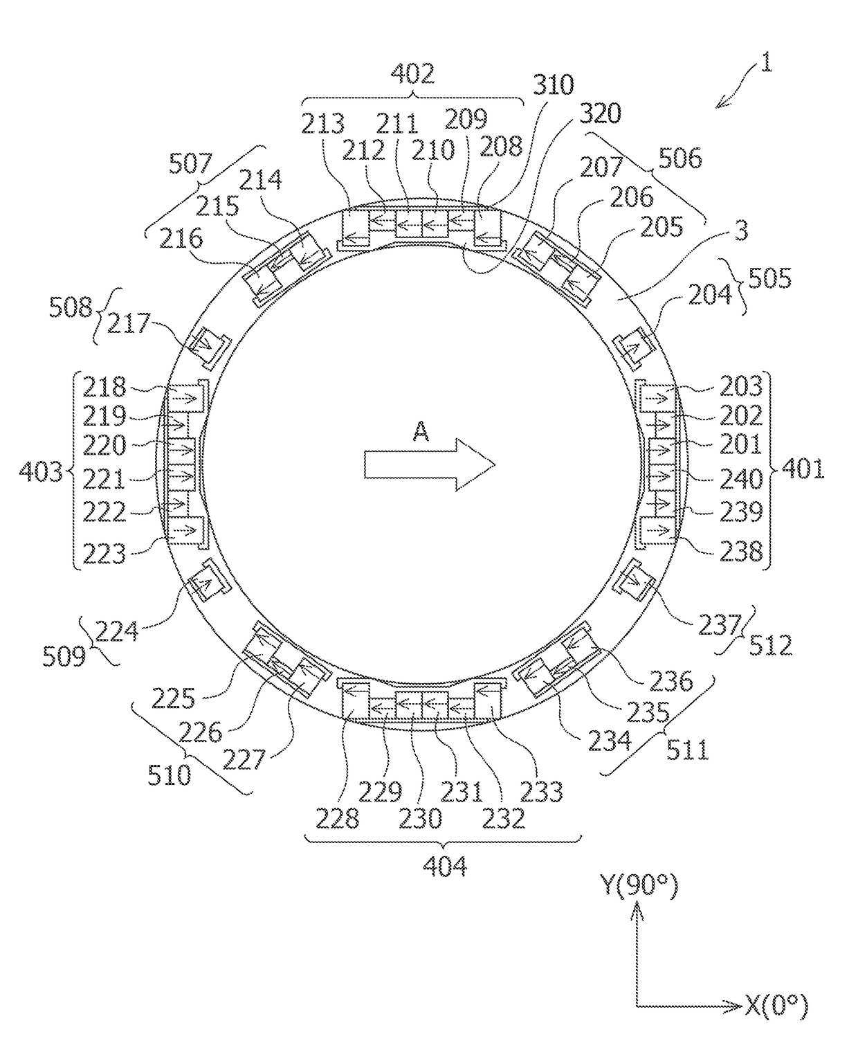
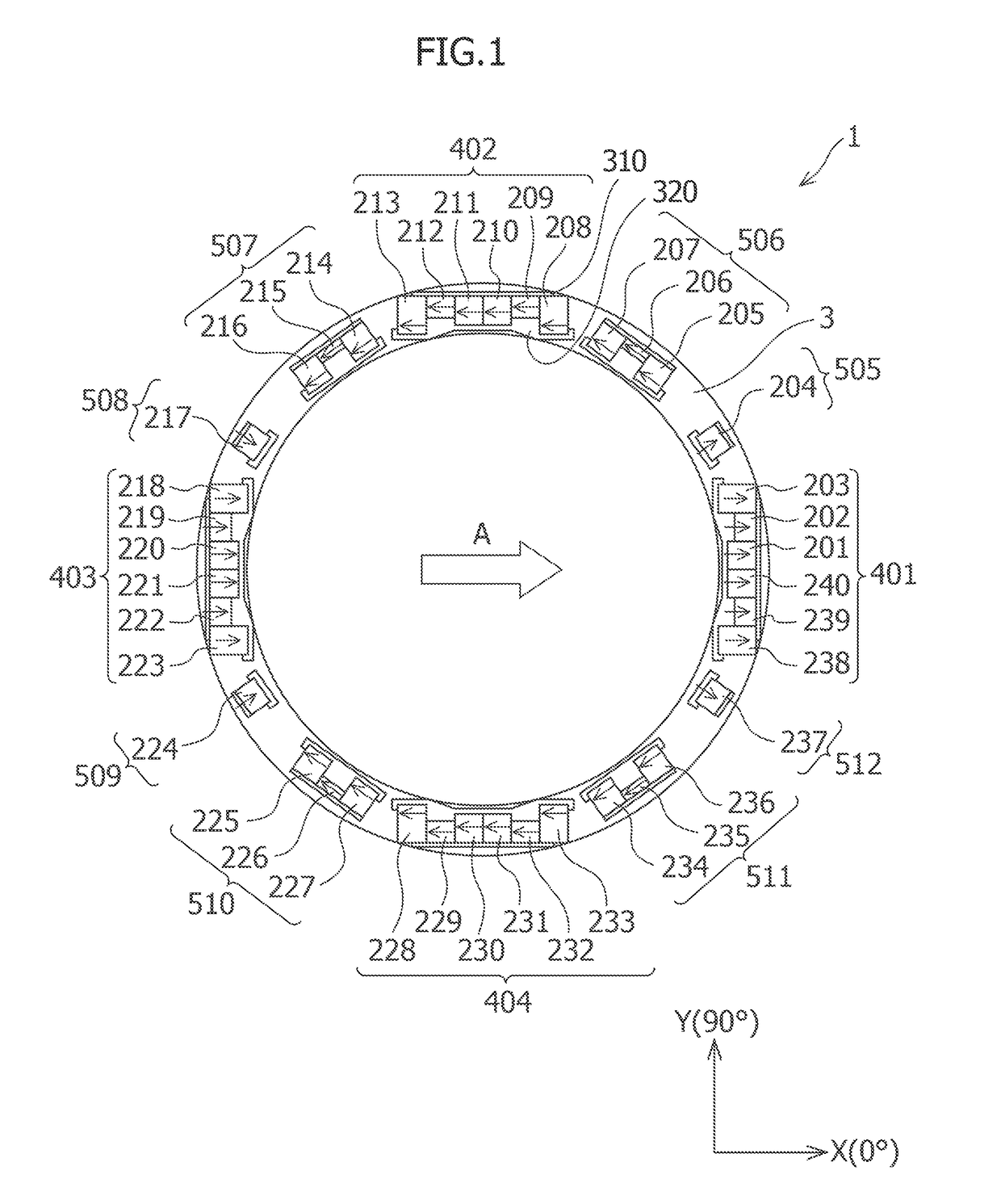
[0064]In Example 1, a dipole ring magnetic field generator shown in FIG. 3 was fabricated. FIG. 3 exhibits a schematic sectional view of the dipole ring magnetic field generator in a plane being perpendicular to the central axis and passing through the central point of the magnetic field generator. A neodymium base sintered rare earth magnet (N45 by Shin-Etsu Chemical Co. Ltd., the magnetic force of 1.28 T) having a rectangular section (the whole shape being a rectangular parallelepiped) was used. A nonmagnetic material (stainless steel, SUS304) was used for the yoke. The yoke was cylindrical, and had an outside diameter of 500 mm, an inside diameter of 430 mm, and a depth (the length in the axial direction) of 648 mm. As shown in FIG. 3, the distance between a pair of permanent magnet units positioned on the opposite sides with respect to the central axis, which was the shortest distance from the side on the outside diameter side of one permanent magnet unit to the side on the outs...


PUM

PropertyMeasurementUnit
angleaaaaaaaaaa
sizeaaaaaaaaaa
sizeaaaaaaaaaa

Abstract

Provided is a dipole ring magnetic field generator capable of generating a substantially unidirectional magnetic field in the internal space of a ring without using permanent magnet pieces having fan-shaped or trapezoidal sections, and as a result, a smaller skew angle therein is achieved. The sections of the permanent magnet pieces are shaped to be rectangular, and a plurality of the rectangular permanent magnet pieces are circularly placed at predetermined positions. Each of first, second, third and fourth permanent magnet units, which are main permanent magnet units, comprises five or more permanent magnet pieces. The first and third permanent magnet units, as well as the second and fourth permanent magnet units, are positioned oppositely from each other with respect to a central axis of the magnetic field generator and have hollow shapes or E-shapes facing against each other in a section perpendicular to the central axis.

Description

BACKGROUND OF THE INVENTION[0001]1. Field of the Invention[0002]The present invention relates to a dipole ring magnetic field generator.[0003]2. Description of the Related Art[0004]A typical dipole ring magnetic field generator comprises a plurality of permanent magnet pieces arranged in such a ring that the magnetization direction of each permanent magnet piece makes one rotation over a half circumference of the ring so as to generate a substantially unidirectional magnetic field in the internal space, wherein each permanent magnetic piece has a magnetic field of the same intensity as that of the unidirectional magnetic field. Such a dipole ring magnetic field generator is used in an extensive range of applications, including a magnetic resonance imager (MRI), a semiconductor device manufacturing process, and a uniform magnetic field generator for basic researches (e.g. JP 2005-56903A). Conventionally, normal conductive electromagnets, superconductive electromagnets and the like ha...

Claims


Application Information

Patent Timeline
Patent Type & Authority Patents(United States)
IPC IPC(8): H01F7/02G01R33/383
CPCH01F7/021G01R33/383H01F7/0221H01F7/0268H01F7/0273H01F7/0278H01F7/0284
Inventor INOUE, TAKANOBUHIGUCHI, DAI
Owner SHIN ETSU CHEM CO LTD
Learn More