Stunner

Active Publication Date: 2017-05-30
JARVIS PROD
View PDF5 Cites 8 Cited by
  • Summary
  • Abstract
  • Description
  • Claims
  • Application Information

AI Technical Summary

Benefits of technology

[0009]Bearing in mind the problems and deficiencies of the prior art, it is therefore an object of the present invention to provid

Problems solved by technology

The catch and other components of such prior designs function well, but in operation some of its components are subject to sliding engageme

Method used


Image

  • Stunner
  • Stunner
  • Stunner

Examples


Embodiment Construction

)

[0055]In describing the preferred embodiment of the present invention, reference will be made herein to FIGS. 3-24 of the drawings in which like numerals refer to like features of the invention.

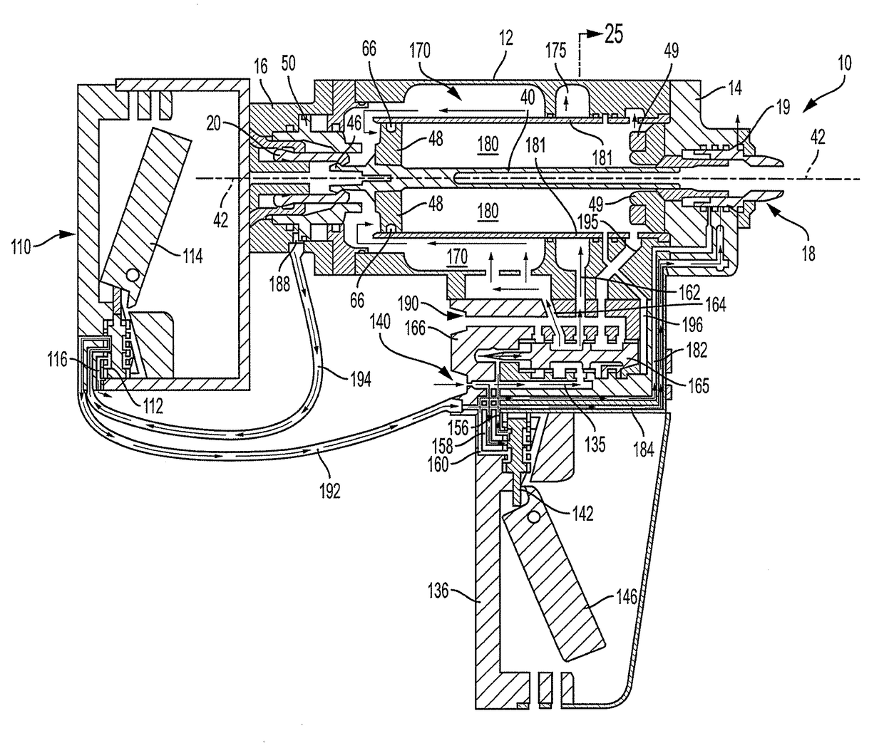
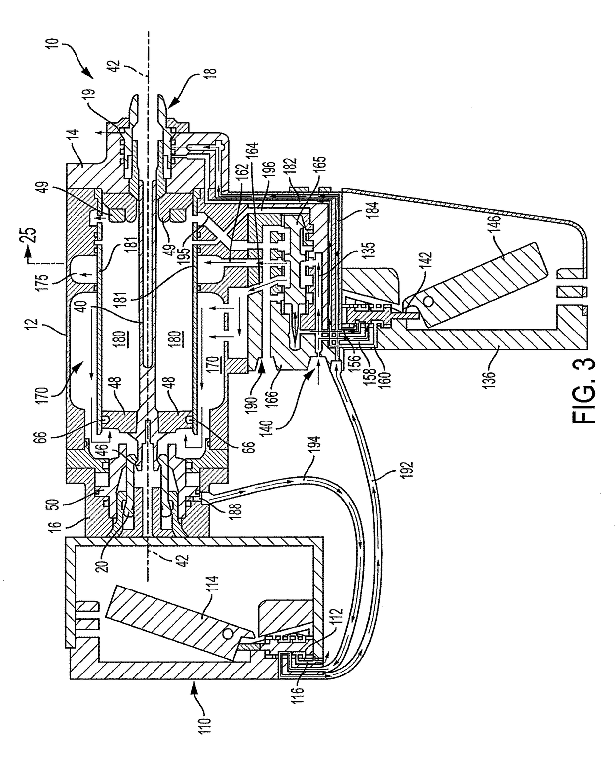
[0056]Structure and operation of the exemplary animal stunner 10 is shown in general in FIGS. 3-8. The stunner 10 includes an outer elongated hollow housing 12, an outer housing nose or front end 14, a tail end 16, a stunning rod 40 and a catch 20 for holding and releasing the stunning rod 40. The portion of the animal stunner 10 having a catch is shown in detail in FIGS. 7 and 8. The forward and rearward directions described herein are with respect to the stunner front end 14, and inward and outward directions described herein are with respect to the longitudinal axis 42. A piston 48 surrounded by an O-ring seal 66 slides within an inner cylindrical chamber 180 forward and rearward along axis 42, and carries stunning rod 40. The rearward end of stunning rod 40 ends in an outward extending l...


PUM


Abstract

A pneumatic animal stunner employing a stunning rod includes a catch mounted within the housing for alternately holding and releasing the stunning rod. A catch piston is disposed adjacent the catch on a side away from the longitudinal axis, and is in sliding contact adjacent the catch end portion and out of contact with the catch body portion. The catch piston slides between a first position urging the catch end portion toward the stunning rod longitudinal axis in the hold position, thereby holding and preventing the stunning rod from being driven forward, and a second position permitting the catch end portion to move to the release position away from the stunning rod longitudinal axis releasing and permitting the stunning rod to be driven forward. Valves control air flow to cause the catch piston to move between the first and second positions.

Description

[0001]This application claims priority to U.S. provisional patent application No. 62 / 357,566 filed on Jul. 1, 2016.BACKGROUND OF THE INVENTION[0002]1. Field of the Invention[0003]This invention relates in general to a pneumatic animal stunner for use in livestock / slaughterhouse operations and more specifically to the catch system for holding and releasing the stunning rod.[0004]2. Description of Related Art[0005]In livestock production plants, it is important to stun and disable an animal for processing. Although numerous methods have been used to stun livestock, captive bolt mechanisms have proven to be the most efficient, inexpensive, and humane way to disable the animal. Particularly, pneumatic captive bolt devices have been used in this capacity.[0006]U.S. Pat. No. 6,135,871 and U.S. Patent Publication No. 2004 / 0209562, the disclosures of which are hereby incorporated by reference, disclose pneumatic animal stunners that, among other things, include a physical catch for the pist...

Claims


Application Information

Patent Timeline
IPC IPC(8): A22B3/00A22B3/02
CPCA22B3/02
Inventor JONES, ARTHURJONES, TRENT
Owner JARVIS PROD
Why Eureka
Try Eureka