Cellular tissue dissection method and liquid ejection device

a cell tissue and liquid ejection technology, applied in the field of cell tissue dissection methods and liquid ejection devices, can solve the problems of fatigue fractures that can occur more easily in the part connecting cells together, and it is difficult to control the depth to which the cellular tissue is dissected

Active Publication Date: 2017-05-30
SEIKO EPSON CORP
View PDF4 Cites 1 Cited by
  • Summary
  • Abstract
  • Description
  • Claims
  • Application Information

AI Technical Summary

Benefits of technology

[0010]According to this application example, the incision is formed at the site where the cellular tissue is to be dissected. Then, the liquid is ejected to the incision, thus expanding the incision. The cellular tissue is dissected by the water pressure of the ejected liquid. When the liquid is ejected to the incision, stress concentrates at the end of the incision. Therefore, even when the water pressure is low, the cellular tissue can be dissected easily.
[0011]An extremely high water pressure is needed when there is no incision. The water pressure at the time of dissecting the surface of the cellular tissue reaches the insides of the cellular tissue. Since the extremely high water pressure is applied to the inside of the cellular tissue, it is difficult to control the depth to which the cellular tissue is dissected. Meanwhile, when the liquid is ejected to the incision, the dissection can be achieved with a lower water pressure and therefore the water pressure can be prevented from reaching deep parts of the cellular tissue. Also, since the incision is formed, dissection in an unintended direction can be avoided. Therefore, the depth to which the cellular tissue is dissected can be controlled easily.Application Example 2
[0013]According to this application example, the liquid is ejected in the form of a pulse flow. With the pulse flow, the pressure fluctuation applied to the cellular tissue can be made greater, compared with a continuous flow. As the pressure fluctuation increases, fatigue fracture can occur more easily in the part connecting cells together. Therefore, the cellular tissue can be dissected easily.Application Example 3
[0015]According to this application example, the liquid is ejected in such a way as to advance obliquely to the tangential direction to the surface of the cellular tissue. The liquid accumulates in the incision at the site where the liquid is ejected. Then, the site where the liquid is applied to the surface is moved in the direction in which the angle formed by the surface and the direction of advancement of the liquid is greater. Therefore, the ejection of the liquid is moved in such a way as to push the liquid accumulating in the incision. Consequently, the liquid pushed by the water pressure heads in the direction of pressing and expanding the incision. Therefore, the incision can be expanded easily.Application Example 4
[0017]According to this application example, the liquid ejection device has the nozzle for ejecting the liquid and the edge portion. The surgical operator can form an incision on the surface of a cellular tissue, using the edge portion, and then eject the liquid from the nozzle toward the incision. Thus, since dissection can be achieved with a low water pressure along the incision at the time of forming the incision, the depth and direction in which the cellular tissue is dissected can be easily controlled. Since the liquid ejection device has the edge portion, the surgical operator can carry out the formation of the incision and the ejection of the liquid, using the liquid ejection device. Thus, the surgical operator need not hold the knife first and then the liquid ejection device. Therefore, the cellular tissue can be dissected with high operability.Application Example 5
[0019]According to this application example, the edge portion is installed side by side with the nozzle. The end of the edge portion is installed, protruding ahead of the end of the nozzle in the direction in which the liquid is ejected. Therefore, the surgical operator can carry out the formation of the incision and the ejection of the liquid without changing the way of holding the liquid ejection device.

Problems solved by technology

Since the extremely high water pressure is applied to the inside of the cellular tissue, it is difficult to control the depth to which the cellular tissue is dissected.
As the pressure fluctuation increases, fatigue fracture can occur more easily in the part connecting cells together.

Method used


Image

  • Cellular tissue dissection method and liquid ejection device
  • Cellular tissue dissection method and liquid ejection device
  • Cellular tissue dissection method and liquid ejection device

Examples


first embodiment

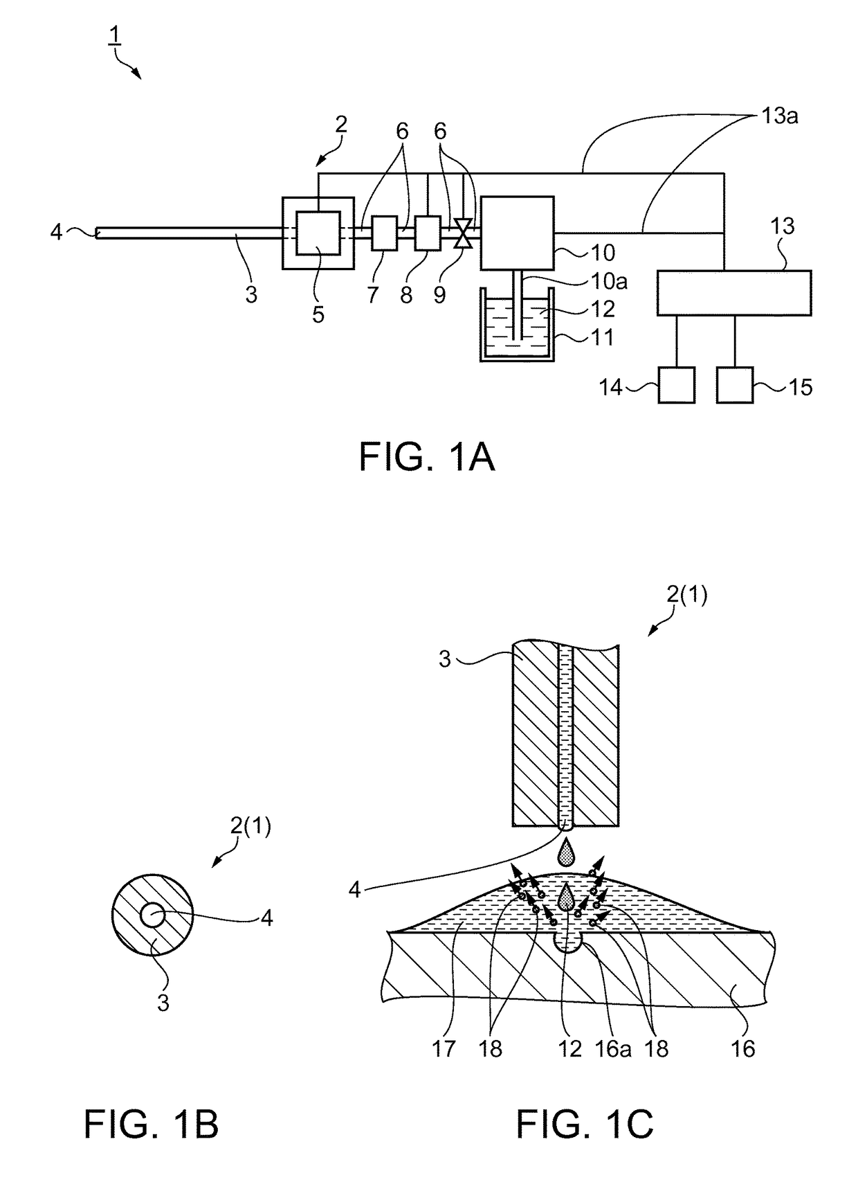
[0029]In this embodiment, a liquid ejection device as a surgical apparatus will be described with reference to FIGS. 1A to 5D. FIG. 1A is a block diagram showing the configuration of the liquid ejection device. FIG. 1B is partial schematic side view showing the structure of a nozzle in the liquid ejection device. The liquid ejection device 1 of this embodiment is a medical apparatus used in a medical institution and has the function of a surgical knife which ejects a fluid to an affected part and thus incises or excises the affected part. The liquid ejection device 1 can also be used for treatment and autopsy of other animals than humans.

[0030]As shown in FIG. 1A, the liquid ejection device 1 has a handpiece 2. The handpiece 2 is a device which the surgical operator holds in his / her hand and operates when carrying out a surgical operation. In other situations than surgical operation, the surgical operator is also referred to as an operator. An ejection tube 3 that is a channel for a...

second embodiment

[0072]Next, an embodiment of a liquid ejection device will be described with reference to the block diagram of FIG. 6 showing the configuration of the liquid ejection device.

[0073]This embodiment is different from the first embodiment in that the pulsation applying part 5 of FIG. 1A is eliminated. The same features as in the first embodiment will not be described further.

[0074]That is, in this embodiment, in a liquid ejection device 62, the tube 6 is connected with the ejection tube 3, as shown in FIG. 6. As the surgical operator turns on the ejection switch 15, the liquid 12 is continuously ejected from the nozzle 4. Again, when the cellular tissue 16 can be dissected, a configuration without the pulsation applying part 5 may be employed. Since the pulsation applying part 5 and the pulsation control unit 50 can be omitted, the liquid ejection device 62 that can be easily manufactured is provided.

third embodiment

[0075]Next, an embodiment of a liquid ejection device will be described with reference to the block diagram of FIG. 7 showing the configuration of the liquid ejection device.

[0076]This embodiment is different from the first embodiment in that an edge portion 64 is installed near the nozzle 4. The same features as in the first embodiment will not be described further.

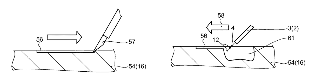
[0077]That is, in this embodiment, in a liquid ejection device 63, the edge portion 64 is installed on the ejection tube 3, as shown in FIG. 7. Thus, the surgical operator can form the incision 56 on the surface of the cellular tissue 16 and eject the liquid 12 toward the incision 56 from the nozzle 4. Since the liquid ejection device 63 has the edge portion 64, the surgical operator can carry out both the formation of the incision 56 and the ejection of the liquid 12, using the liquid ejection device 63. Therefore, since the surgical operator need not hold a plurality of tools one after another, the cellular tissue 16 c...


PUM


Abstract

An incision is formed at a site where a cellular tissue is to be dissected. A liquid is ejected to the incision. The incision is expanded. The cellular tissue is dissected. The liquid is ejected in the form of a pulse flow. The liquid is ejected in such a way as to advance obliquely to a tangential direction to a surface of the cellular tissue. A site where the liquid is applied to the surface is moved in a direction in which an angle formed by the surface and the direction of advancement of the liquid is greater.

Description

[0001]This application claims the benefit of Japanese Patent Application No. 2014-120268, filed on Jun. 11, 2014. The content of the aforementioned application is incorporated herein by reference in its entirety.BACKGROUND[0002]1. Technical Field[0003]The present invention relates to a cellular tissue dissection method and a liquid ejection device.[0004]2. Related Art[0005]Dissection processing is broadly employed in which a cellular tissue in a muscle, organ, tunic, blood vessel, tumor or the like is separated, severed and thus excised or stripped off. In this processing, a metallic surgical knife, electric surgical knife, laser surgical knife, water jet surgical knife or the like is used.[0006]The water jet surgical knife dissects a cellular tissue with the impact energy of a water jet flow. The water jet surgical knife is able to dissect only the tissue without damaging any nerves, blood vessels or the like. JP-A-2008-82202 discloses a liquid ejection device as a water jet surgic...

Claims


Application Information

Patent Timeline
Patent Type & Authority Patents(United States)
IPC IPC(8): A61B17/32A61B17/3203A61B17/00
CPCA61B17/3203A61B2017/00154
Inventor KOJIMA, HIDEKIENDO, TOSHIKINAKAGAWA, ATSUHIROTEIJI, TOMINAGA
Owner SEIKO EPSON CORP
Why Eureka
Try Eureka