Control apparatus for transmission for vehicle

a technology for controlling apparatus and transmission, which is applied in the direction of gearing control, gearing elements, gearing control, etc., can solve the problems of engine stall, disturbance to idling rotational speed control, etc., and achieve the effect of limiting the torque generated as a result of shifting, and restricting the rotational speed of the driving force sour

Active Publication Date: 2017-05-30
TOYOTA JIDOSHA KK
View PDF9 Cites 1 Cited by
  • Summary
  • Abstract
  • Description
  • Claims
  • Application Information

AI Technical Summary

Benefits of technology

[0004]This invention has been made in view of the aforementioned technical problem. It is an object of this invention to provide a control apparatus that can prevent or restrain the rotational speed of a driving force source from abruptly changing and the driving force source from going into a stall, as a result of shifting in a transmission that transmits no torque to an output shaft.
[0012]In this invention, even when the speed ratio obtained by the continuously variable speed change mechanism is changed with the continuously variable speed change mechanism transmitting no torque to the driving wheel, the shifting speed is limited to or below the predetermined upper-limit speed, and the inertia torque generated as a result of shifting is thereby limited. As a result, the amplitude of fluctuations in the torque applied as a load to the driving force source that is subjected to idling rotational speed control decreases. Thus, the rotational speed of the driving force source can be restrained from fluctuating, and also, the driving force source can be restrained from going into a stall.
[0013]In particular, when the aforementioned upper-limit speed is determined based on the output torque of the driving force source that is subjected to the idling rotational speed control, the rotational speed of the driving force source, and the moment of inertia of an output-side rotary member in the continuously variable speed change mechanism, the rotational speed of the driving force source can be more effectively restrained from fluctuating, and the driving force source can be more effectively restrained from going into a stall.
[0014]Furthermore, if the control apparatus of this invention is configured to increase the output torque of the driving force source in the case where the aforementioned shifting is performed above the output torque of the driving force source in the case where the shifting is not performed, the rotational speed of the driving force source is unlikely to decrease even when the aforementioned inertia torque is applied to the driving force source. Therefore, the shifting speed can be enhanced.
[0015]By setting the amount of increase in the output torque in that case to the amount determined based on the rotational speed of the driving force source, the moment of inertia of the output-side rotary member in the continuously variable speed change mechanism, and the speed at which the speed ratio is changed, the shifting speed of the continuously variable speed change mechanism can be enhanced while restraining the output torque of the driving force source from excessively increasing.

Problems solved by technology

Therefore, for example, when the idling rotational speed of the engine as a driving force source is controlled, the changes in torque resulting from the aforementioned shifting act as a disturbance to idling rotational speed control.
Thus, an abrupt change in idling rotational speed and the occurrence of engine stall are possible.

Method used


Image

  • Control apparatus for transmission for vehicle
  • Control apparatus for transmission for vehicle
  • Control apparatus for transmission for vehicle

Examples


Embodiment Construction

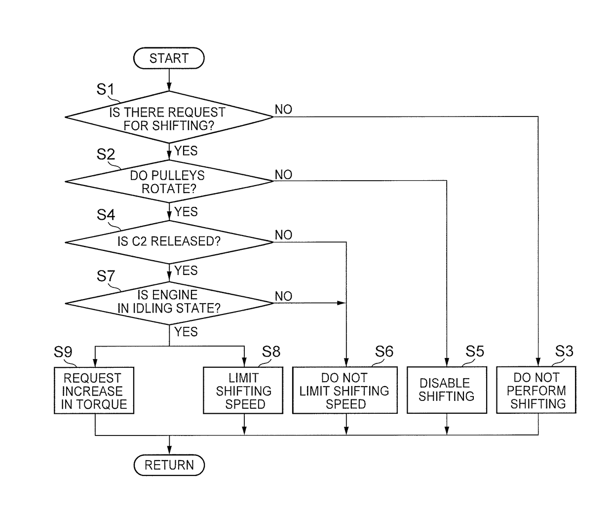
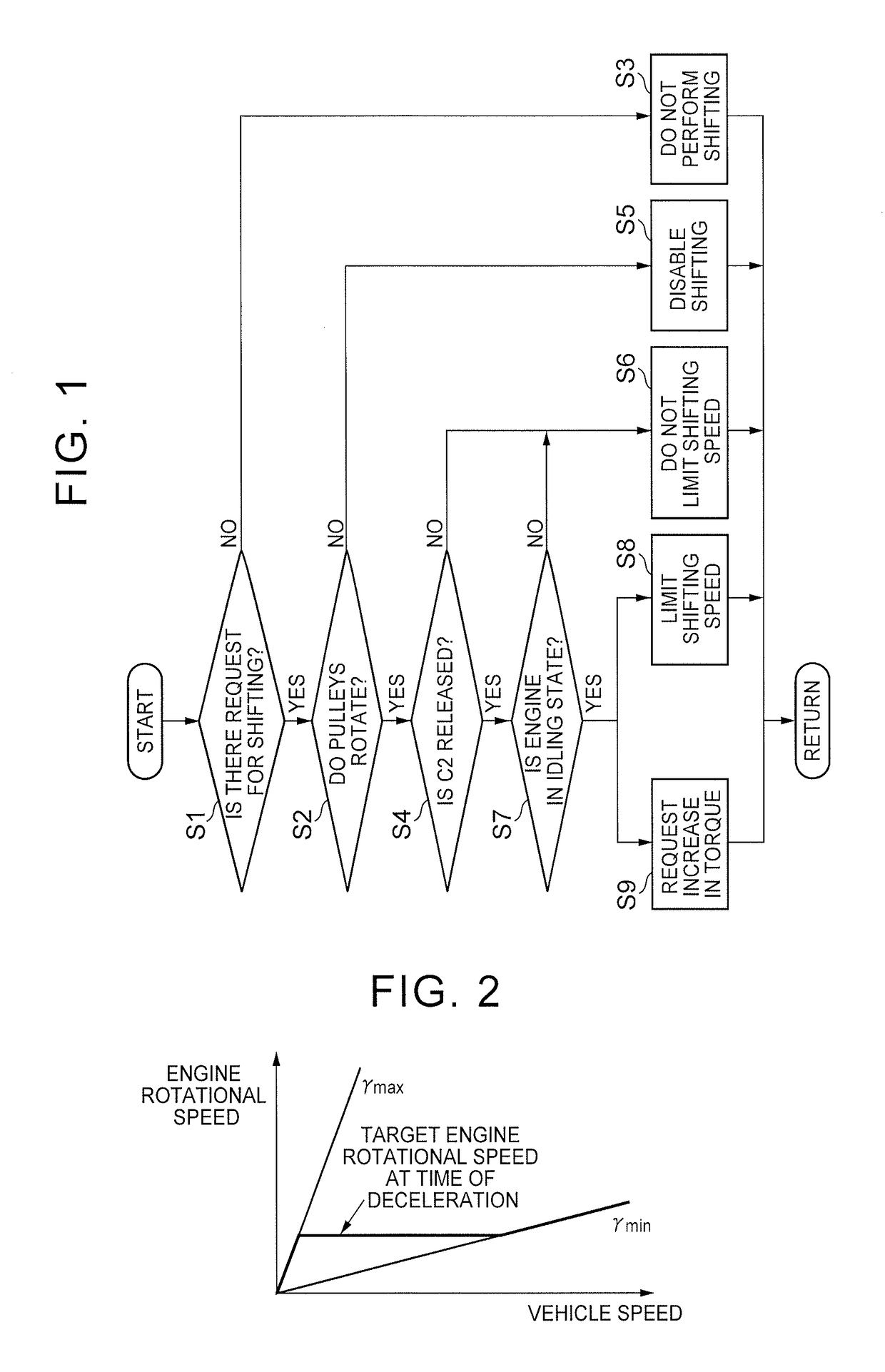
[0025]This invention is applicable to a vehicle that is equipped with a driving force source that is subjected to idling rotational speed control, and a continuously variable speed change mechanism that is coupled to an output side of the driving force source and can control the speed of shifting. In this vehicle, the transmission of torque from the continuously variable speed change mechanism to driving wheels can be appropriately blocked. Accordingly, concrete examples of the driving force source include an internal combustion engine such as a gasoline engine or the like, and a hybrid-type driving force source that is equipped with the internal combustion engine and a motor. Besides, a belt-type or toroidal-type transmission is an example of the continuously variable speed change mechanism. The transmission to which this invention is applied may be a transmission having a single motive power transmission path including a continuously variable speed change mechanism, or a transmiss...


PUM


Abstract

A vehicle transmission has a continuously variable speed change mechanism provided between an input shaft to which a torque output by a driving force source is transmitted and an output shaft from which a torque is output to a driving wheel. The transmission is able to selectively block torque transmission between the mechanism and the output shaft. The mechanism is rotated by the driving force source with torque transmission between the mechanism and the output shaft blocked. A control apparatus limits a shifting speed of the mechanism to or below an upper-limit speed determined in advance in a case where a speed ratio of the mechanism is changed with the mechanism rotated by the driving force source that is subjected to idling rotational speed control, while the mechanism is blocked from the output shaft such that no torque is transmitted between the mechanism and the output shaft.

Description

TECHNICAL FIELD[0001]The invention relates to an apparatus that controls a transmission for a vehicle that increases / reduces and outputs a driving force output from a driving force source.BACKGROUND ART[0002]There is known a vehicle in which the transmission of torque from a transmission to driving wheels can be blocked with a driving force source such as an engine or the like and the transmission coupled to each other in such a manner as to enable the transmission of torque, and an example thereof is described in Japanese Utility Model Application Publication No. 62-45455 (JP 62-45455 U). In the transmission described in this publication, a V-belt shifting device and a directly-coupled gear are arranged in parallel with each other between an input shaft and a countershaft. A primary shaft of the V-belt shifting device is coupled to the input shaft, and a clutch is provided coaxially with a secondary shaft of the V-belt shifting device. The transmission is configured to block the tr...

Claims


Application Information

Patent Timeline
Patent Type & Authority Patents(United States)
IPC IPC(8): B60W10/06B60W10/107F16H61/70B60W30/19F16H61/04F16H59/22F16H61/662F16H37/02
CPCB60W30/19B60W10/06B60W10/107F16H61/04F16H61/66272F16H61/70B60W2510/0638B60W2510/1095B60W2710/0666F16H37/022F16H59/22F16H61/662F16H61/16F16H61/66259B60W2710/065
Inventor ISHIKAWA, SHUHEIKIMURA, MOTONORIAYABE, ATSUSHI
Owner TOYOTA JIDOSHA KK
Why Eureka
Try Eureka