Thermoacoustic transducer apparatus including a transmission duct

a technology of transmission ducts and transducers, which is applied in the direction of gas cycle refrigeration machines, lighting and heating apparatuses, stirling engines, etc., can solve the problems of complex structural architecture, and achieve the effect of reducing heat transfer and minimizing overall losses in the apparatus

Active Publication Date: 2017-05-30
ETALIM
View PDF61 Cites 5 Cited by
  • Summary
  • Abstract
  • Description
  • Claims
  • Application Information

AI Technical Summary

Benefits of technology

[0018]The mechanical spring may include a resilient wall portion coupled between the at least one diaphragm and a chamber wall of one of one of the compression chamber and the expansion chamber, the resilient wall portion being operable to provide a seal for containing working gas within the chamber while facilitating the resilient displacement of the at least one diaphragm.
[0021]An extent of at least one of the compression chamber and the expansion chamber may be selected to provide a desired acoustic impedance for facilitating acoustic coupling between the chamber and the respective transmission duct.
[0024]The at least one diaphragm may have a thickness profile across the diaphragm that may be selected to cause stress concentrations in the diaphragm to be reduced.
[0029]The thermal converter may include a thermal buffer for reducing heat transfer between the thermal converter and the mechanical converter, the thermal buffer being in fluid communication between the flow passage and the transmission duct extending between the expansion chamber and the flow passage.
[0030]During acoustic power flow between the compression chamber and the expansion chamber a standing wave component and a traveling wave component may be established within the acoustic power loop and the cross-sectional areas of the transmission ducts may be selected to cause the relative magnitudes of the standing wave component and traveling wave component to be apportioned to minimize overall losses in the apparatus.

Problems solved by technology

However such temperature increases may require implementation of a more complex structural architecture and / or the use of specialized high temperature materials.

Method used


Image

  • Thermoacoustic transducer apparatus including a transmission duct
  • Thermoacoustic transducer apparatus including a transmission duct
  • Thermoacoustic transducer apparatus including a transmission duct

Examples


Embodiment Construction

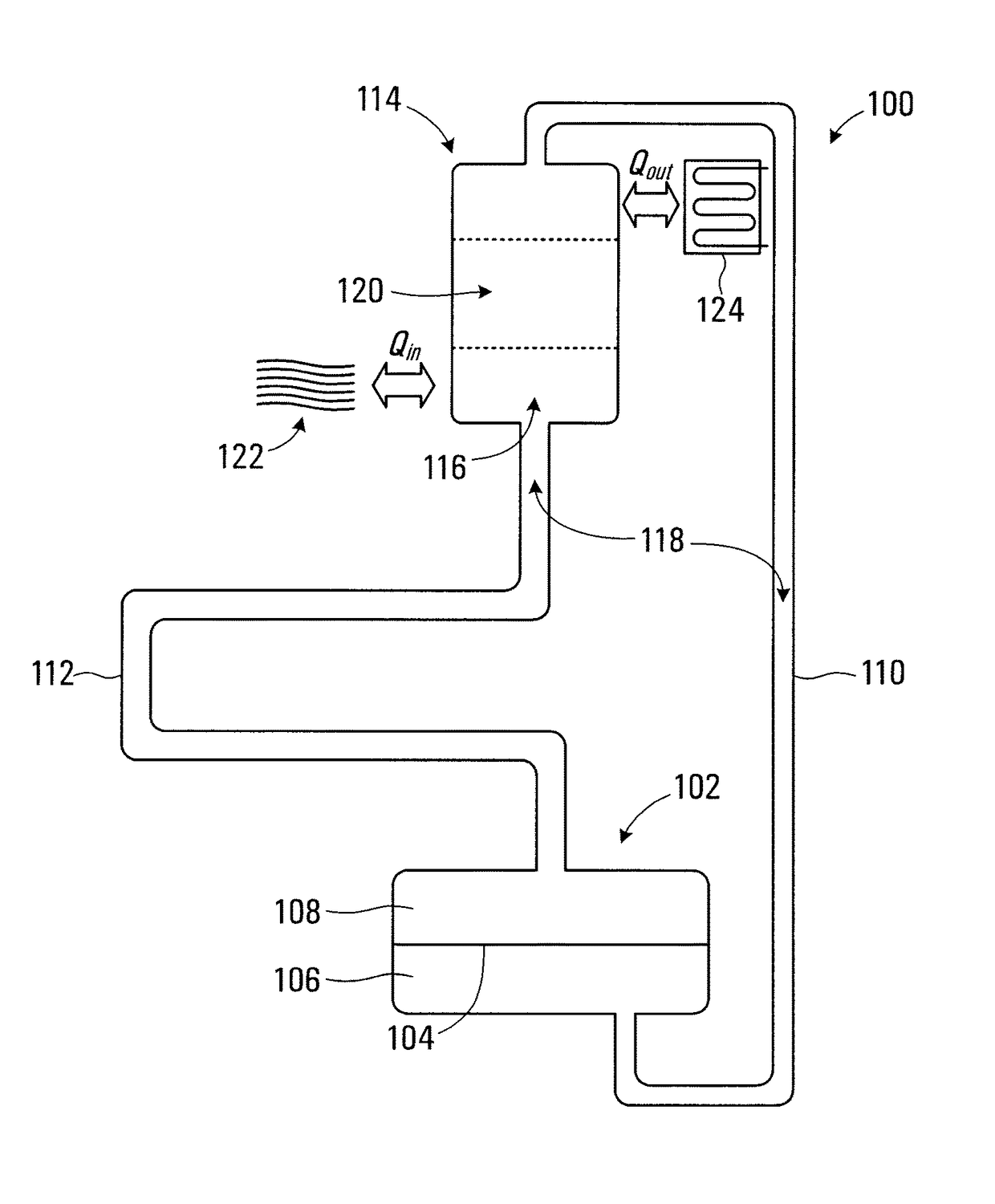
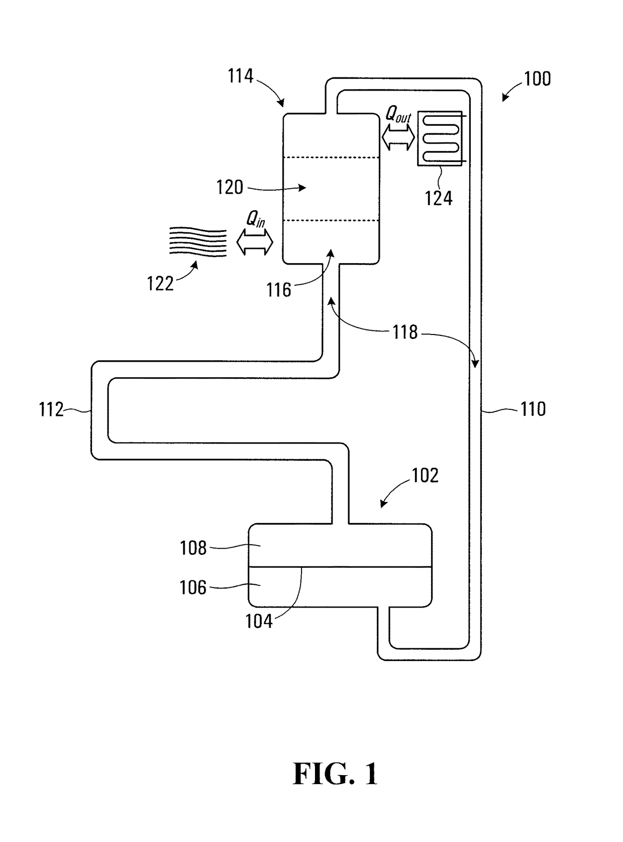
[0056]Referring to FIG. 1, a thermoacoustic transducer apparatus according to a first embodiment of the invention is shown generally at 100. The apparatus 100 includes a mechanical converter 102 operable to provide power conversion between acoustic power and mechanical power. The mechanical converter 102 includes a diaphragm 104 defining a compression chamber 106 and an expansion chamber 108 within the mechanical converter. The diaphragm has an associated diaphragm surface area As.

[0057]The apparatus 100 also includes a thermal converter 114 including a flow passage 116. The flow passage 116 includes a regenerator portion 120 thermally coupled to provide power conversion between acoustic power and thermal power. The regenerator portion 120 has a regenerator flow area AR.

[0058]The mechanical converter 102 is in fluid communication with the flow passage 116 of the thermal converter 114 through transmission ducts 110 and 112. The transmission duct 110 extends between the compression ch...


PUM


Abstract

A thermoacoustic transducer includes a mechanical converter providing power conversion between acoustic and mechanical power and includes a diaphragm defining a compression and an expansion chamber. A thermal converter including a flow passage having a regenerator portion is thermally coupled for conversion between acoustic and thermal power. The mechanical converter is in fluid communication with the flow passage through transmission ducts completing an acoustic power loop having a volume containing a working gas. A transmission duct cross-sectional area is less than a regenerator flow area, which is less than a diaphragm surface area. The diaphragm undergoes resilient displacement causing pressure oscillations within the volume. The power loop is configured to cause one location along the loop to have anti-phase pressure oscillations to pressure oscillations in the mechanical converter.

Description

RELATED APPLICATIONS[0001]This application is the U.S. National Stage of International Application No. PCT / CA2013 / 000794, filed Sep. 17, 2013, published in English, and claims the benefit of U.S. Provisional Application No. 61 / 702,918, filed on Sep. 19, 2012, the entire teachings of the above applications are incorporated herein by reference.BACKGROUND OF THE INVENTION[0002]1. Field of Invention[0003]This invention relates generally to thermoacoustic transducers and more particularly to a thermoacoustic transducer for converting between thermal energy and mechanical energy.[0004]2. Description of Related Art[0005]Thermoacoustic transducers may be configured to operate as a heat engine where thermal energy is received and the transducer converts the thermal energy into mechanical energy, which may be used to drive an electrical generator, for example. Alternatively a thermoacoustic transducer may be configured to operate as a heat pump where mechanical energy is received and the tran...

Claims


Application Information

Patent Timeline
Patent Type & Authority Patents(United States)
IPC IPC(8): F03G7/00F02G1/043F25B9/14
CPCF03G7/002F02G1/043F25B9/14F02G2243/00F25B2309/1403
Inventor STEINER, THOMAS WALTERMEDARD DE CHARDON, BRIACGOTTFRIED, KRISTJAN TODKLOPFER, RONALD GREGORY
Owner ETALIM
Why Eureka
Try Eureka