Electric flameless candle

a flameless candle and electric technology, applied in the field of electric flameless candles, can solve the problems of affecting air quality and limitations of traditional candles, and achieve the effect of avoiding fire or air pollution

Active Publication Date: 2017-05-30
ZHU HAI FU YUN LIGHTING IND CO LTD
View PDF13 Cites 7 Cited by
  • Summary
  • Abstract
  • Description
  • Claims
  • Application Information

AI Technical Summary

Benefits of technology

[0007]It is an object of the present invention to provide an electric flameless candle which

Problems solved by technology

However, the traditional candle has some limits; for example, the traditional candle should not be used in a flammable environment, and when a traditional candle is used

Method used


Image

  • Electric flameless candle
  • Electric flameless candle
  • Electric flameless candle

Examples


first embodiment

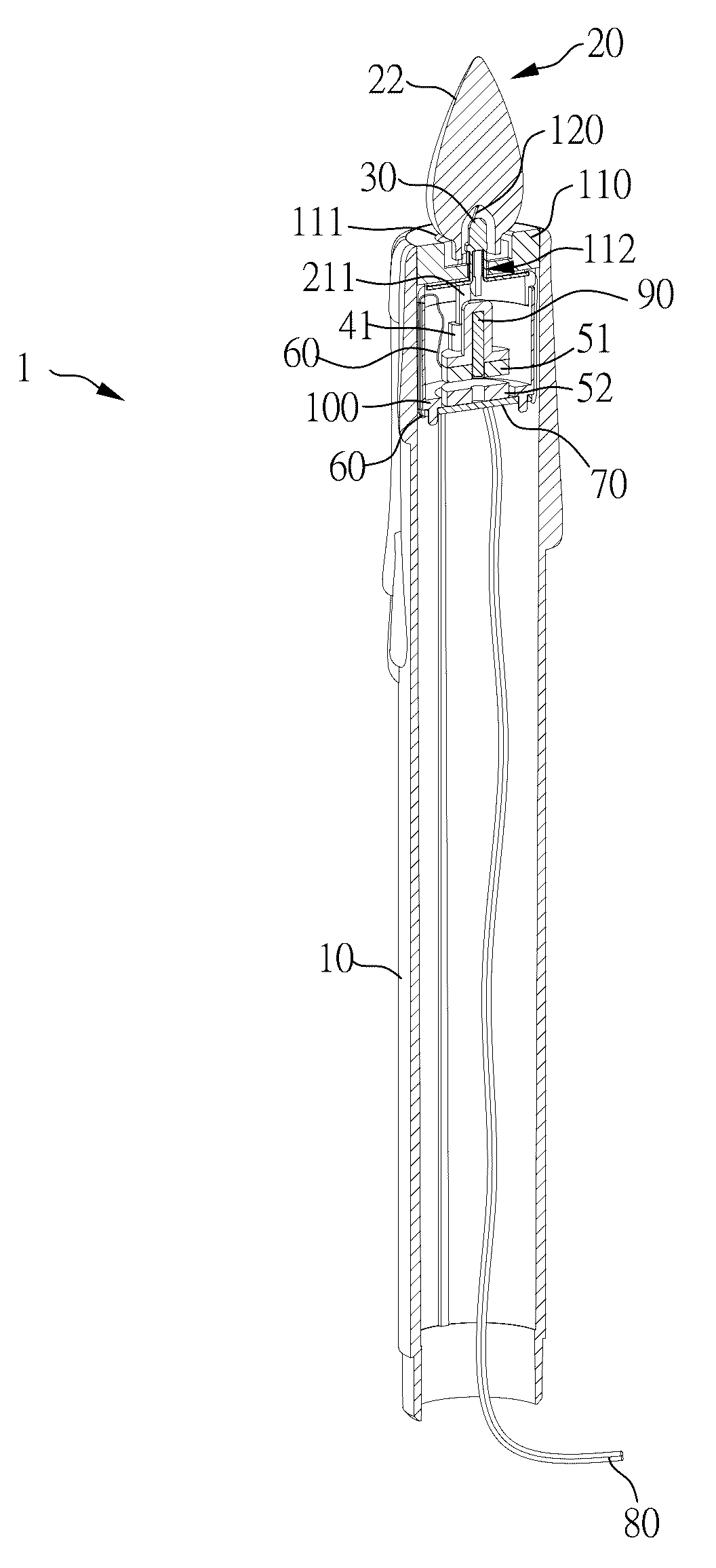
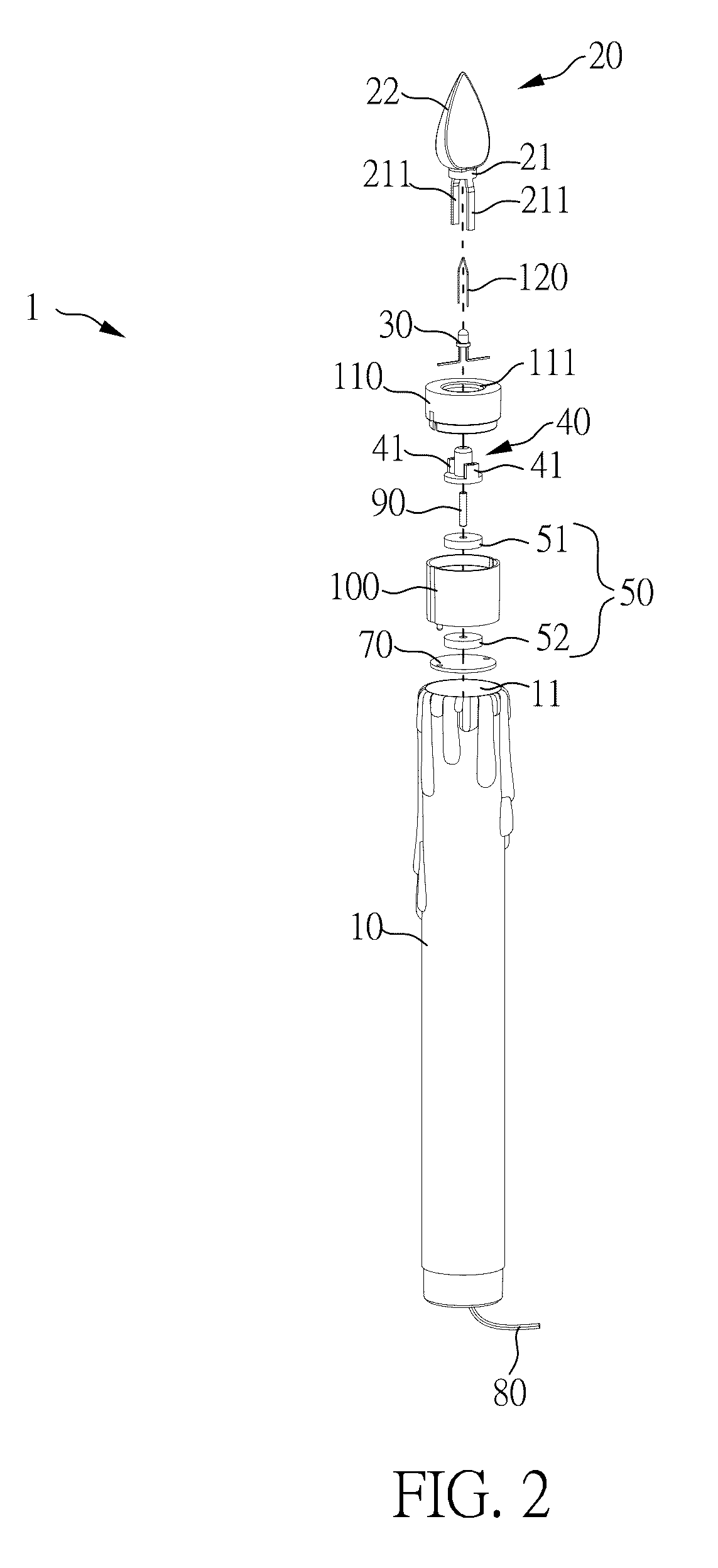
[0034]In the present invention, the connecting unit 40 is connected to the electromagnetic sway module 50 and the translucent shell 20. The connecting unit 40 includes two correspondingly connecting units 41. The two correspondingly connecting units 41 are two slots; the two column-shaped base connecting units 211 pass through the hole 112 to respectively connect to the two slots of the correspondingly connecting units 41; whereby, when the electromagnetic sway module 50 sways, the electromagnetic sway module 50 causes the translucent shell 20 to sway via the connection of the connecting unit 40. However, the amount of the correspondingly connecting unit 41 is not limited to that design; the amount can be changed according to the amount of the base connecting units 211.

[0035]As shown in FIG. 2 to FIG. 6, in the first embodiment of the present invention, the electromagnetic sway module 50 is used for causing the translucent shell 20 to sway and thereby generate the lighting effect of...

second embodiment

[0040]Please refer to FIG. 8 regarding the electric flameless candle of the present invention. FIG. 8 illustrates a partial drawing of the electric flameless candle in the present invention.

[0041]As shown in FIG. 8 the difference between the first embodiment and the second embodiment is that, in the second embodiment, the electric flameless candle 1a does not include the supporting unit 120 (as shown in FIG. 3); furthermore, the light emitting unit 30a does not has the dome top, and the light emitting unit 30a includes a tip 31. The tip 31 touched and supports the bottom of the translucent shell 20; whereby, when the electromagnetic sway module 50 sways, the tip 31 can let the translucent case 22 of the translucent shell 20 be stable via the supporting, to prevent the translucent case 22 to be affected by the swaying of the electromagnetic sway module 50 and to be gradually loose.

[0042]Via the design of the electric flameless candle 1 of the present invention, the shape of a real ca...


PUM


Abstract

An electric flameless candle is disclosed; the electric flameless candle includes a case, a translucent shell positioning unit, a translucent shell, a light emitting unit, a connecting unit, an electromagnetic sway module, a circuit board and a power unit. The case includes an opening. The translucent shell positioning unit is located at the opening. The translucent shell is located on the translucent shell positioning unit and includes a translucent shell base. The light emitting unit is located on the translucent shell base and in the translucent case. The connecting unit is connected to the translucent shell base. The electromagnetic sway module is located in the case. The electromagnetic sway module includes a first sway unit and a second sway unit. The second sway unit is connected to the fixing stand and located under the first sway unit. The circuit board is located in the case.

Description

BACKGROUND OF THE INVENTION[0001]1. Field of the Invention[0002]The present invention relates to an electric flameless candle; more particularly, the present invention relates to an electric flameless candle which provides the effect of a swaying candle flame without risk of fire or air pollution.[0003]2. Description of the Related Art[0004]In daily life, people sometimes may light a traditional candle to increase the comfort and relaxed atmosphere of a living space; in addition, in a church or a temple, people may also light a candle for praying. The flame of a traditional candle will sway with the airflow, and the light of the swaying candle flame makes the atmosphere more romantic and relaxed.[0005]However, the traditional candle has some limits; for example, the traditional candle should not be used in a flammable environment, and when a traditional candle is used, it should not be left unattended due to the risk of fire. Furthermore, the combustion of a traditional candle gener...

Claims


Application Information

Patent Timeline
IPC IPC(8): B60Q1/14F21S10/04F21V3/00F21V23/02F21V23/00F21S6/00F21Y115/10
CPCF21S10/046F21S6/001F21V3/00F21V23/02F21V23/003F21Y2115/10F21V14/00F21V17/10F21W2121/00F21V3/02F21Y2101/00
Inventor CHEN, SU-HUALAI, CHI-SHIH
Owner ZHU HAI FU YUN LIGHTING IND CO LTD
Why Eureka
Try Eureka