Electromagnetic vector sensors (EMVS) apparatus method and system

Active Publication Date: 2017-05-30
US GOVT REPRESENTED BYSEC OF THENAVYCHIEF OF NAVALRES
View PDF4 Cites 1 Cited by
  • Summary
  • Abstract
  • Description
  • Claims
  • Application Information

AI Technical Summary

Benefits of technology

[0008]An electromagnetic vector sensor (EMVS) system, as disclosed herein, comprises a plurality of EMVS devices each consisting of a plurality of loop antenna elements spatially and orthogonally integrated with a plurality of dipole antenna elements, while maintaining electrical isolation from the plurality of dipole antenna elements. This EMVS configuration of spatially orthogonally integrated antenna elements is mounted on a rotatably adjustable platform having a true north orientation; further having active circuitry residing in antenna holding housings to couple the RF signals from the loops/dipoles to various receivers. Also having program code and executable instructions in a pl

Problems solved by technology

However, current devices exhibit poor isolation characteristics between the multiple antenna elements (i.e., the dipole and loop elements) and inadequately res

Method used


Image

  • Electromagnetic vector sensors (EMVS) apparatus method and system
  • Electromagnetic vector sensors (EMVS) apparatus method and system
  • Electromagnetic vector sensors (EMVS) apparatus method and system

Examples


Embodiment Construction

[0060]Preferred exemplary embodiments of the present invention are now described with reference to the figures, in which like reference numerals are generally used to indicate identical or functionally similar elements. While specific details of the preferred exemplary embodiments are discussed, it should be understood that this is done for illustrative purposes only. A person skilled in the relevant art will recognize that other configurations and arrangements can be used without departing from the spirit and scope of the preferred exemplary embodiments. It will also be apparent to a person skilled in the relevant art that the exemplary embodiments can also be employed in other applications. Further, the terms “a”, “an”, “first”, “second” and “third” etc. used herein do not denote limitations of quantity, but rather denote the presence of one or more of the referenced items(s).

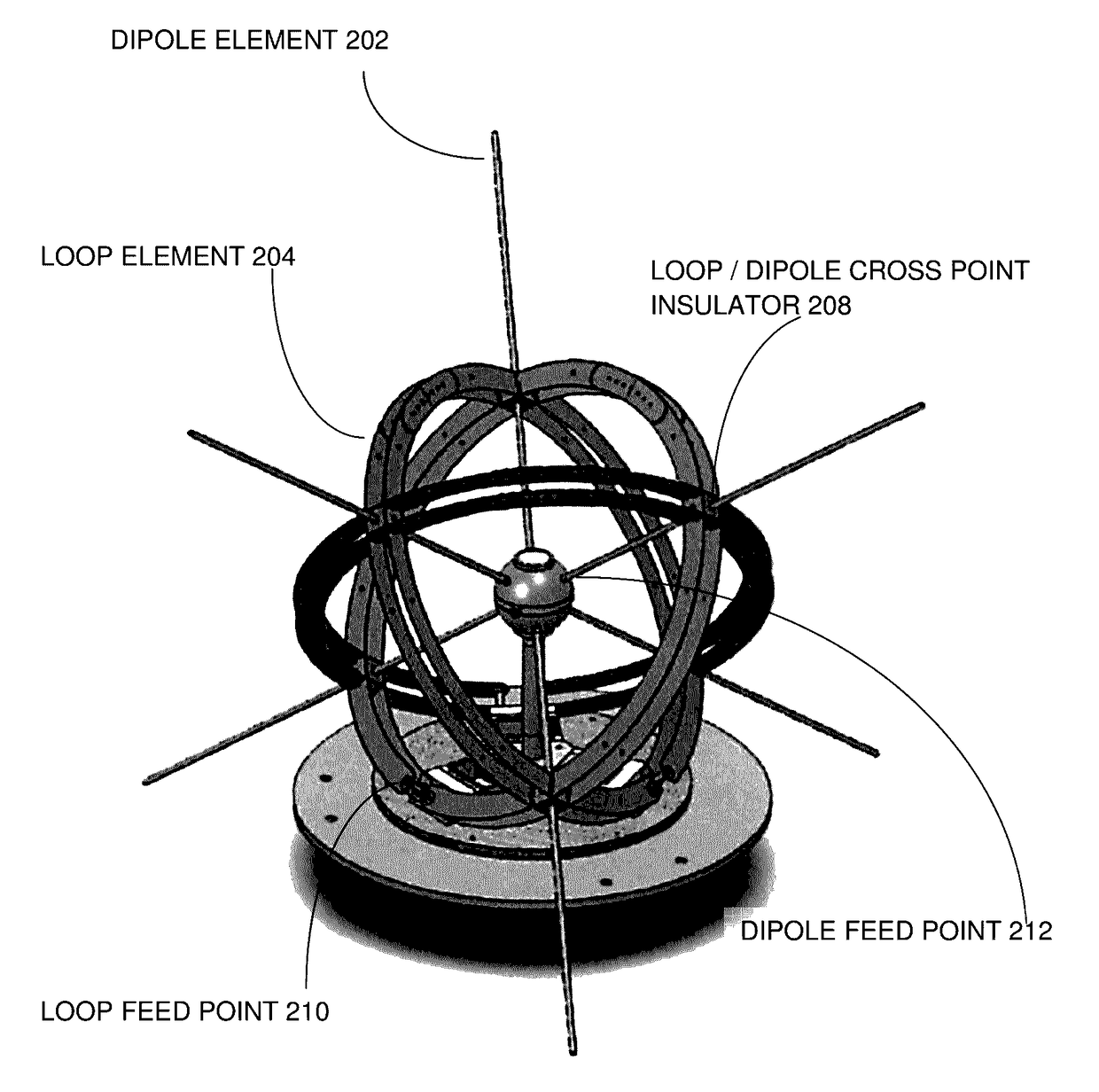
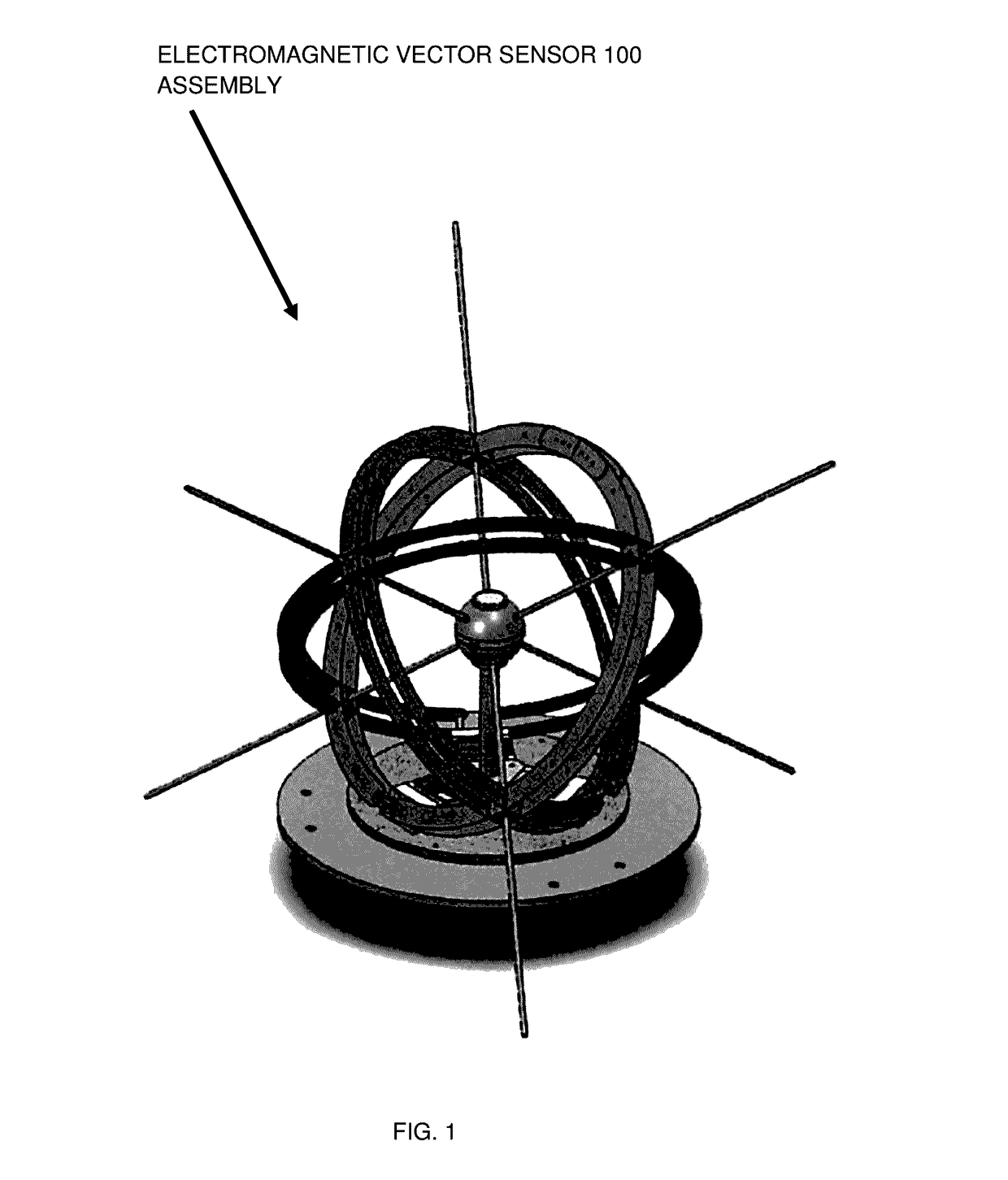
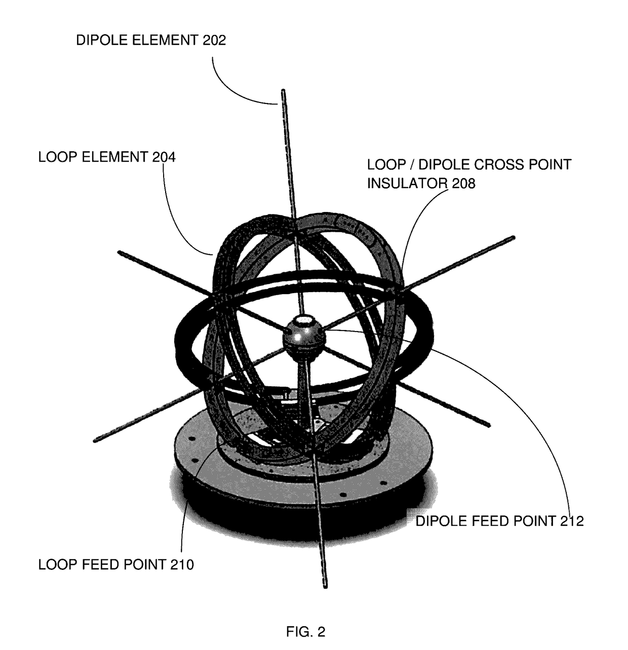
[0061]Referring to FIG. 1, FIG. 2, and FIG. 3, it can be seen that FIG. 1 illustrates an isometric view of...


PUM


Abstract

An electromagnetic vector sensor (EMVS) system, having a plurality of EMVS devices consisting of a plurality of loop antenna elements spatiatally orthogonally integrated with and electrically isolated from a plurality of dipole antenna elements, mounted on a rotatably adjustable platform having a true north orientation, including active circuitry residing in antenna housings, and external executing software programs causing the active circuitry in cooperation with the EMVS device and receivers to determine angle of arrival and resolution of incoming wave vectors and polarization of incoming signals and to perform accurate high frequency geolocation signal processing; the programs which perform calibration and antenna element placement determination operations, also cause the system to collect data of known transmitted high frequency skywave signals, and estimate direction of arrival of unknown signals by detecting, resolving and measuring components of an electric field and a magnetic field at a single point.

Description

RELATED APPLICATIONS[0001]This U.S. patent application is related to U.S. Provisional Application for Patent No. 61 / 788,650 for Electromagnetic Vector Sensors (EMVS) Apparatus Method and System, filed on Mar. 15, 2013 (Mar. 15, 2013), having the same inventor or joint inventor as the instant application, and where the afore mentioned provisional application for patent is incorporated by reference and relied upon herein in its entirety.FIELD OF THE INVENTION[0002]The present invention relates in general to radio communications and antenna devices which can be used in direction finding applications. More particularly, this invention provides a simple means to integrate a series of dipole elements with a series of loop elements such that electromagnetic interactions between the dipole and loop elements are minimized.BACKGROUND OF THE INVENTION[0003]The ability to discriminate polarization states of an incoming wavefront has led to the development of various sensor designs which can be ...

Claims


Application Information

Patent Timeline
IPC IPC(8): H01Q21/24H01Q21/26H01Q7/00H01Q9/22H01Q1/12G01S3/14H04B7/10H01Q21/06
CPCG01S3/143H01Q1/125H01Q7/00H01Q9/22H01Q21/24H01Q21/26
Inventor PARENT, MARK G.LEE, WILLIAM
Owner US GOVT REPRESENTED BYSEC OF THENAVYCHIEF OF NAVALRES
Why Eureka
Try Eureka