Display apparatus

a technology of display apparatus and display screen, which is applied in the field of display screen, can solve the problems of poor performance of dark state and affect display quality, and achieve the effect of reducing light leakage and favorable display quality

Inactive Publication Date: 2017-05-30
AU OPTRONICS CORP +1
View PDF16 Cites 8 Cited by
  • Summary
  • Abstract
  • Description
  • Claims
  • Application Information

AI Technical Summary

Benefits of technology

[0007]The invention of the disclosure is directed to a display apparatus disposed with an optical film having an optical axis shafted by an angle, so to reduce its light leakage for providing a favorable display quality.
[0012]Based on above, in the display apparatus according to embodiments of the invention, which is disposed with an optical film having an optical axis shafted by an angle in which the angle is 1° to 9°. As a result, the light leakage generated by the display apparatus can be reduced so as to enhance the display contrast ratio of the display apparatus for improving the display quality.

Problems solved by technology

However, when a light leakage occurs on the display apparatus, the dark state may have a poor performance which affects the display quality.

Method used


Image

  • Display apparatus
  • Display apparatus
  • Display apparatus

Examples


first embodiment

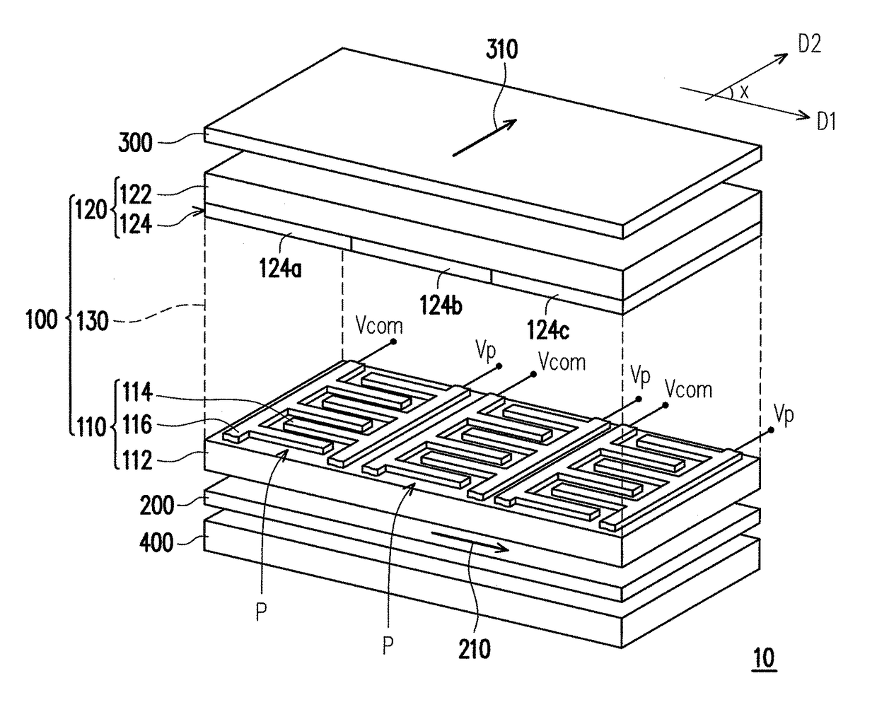
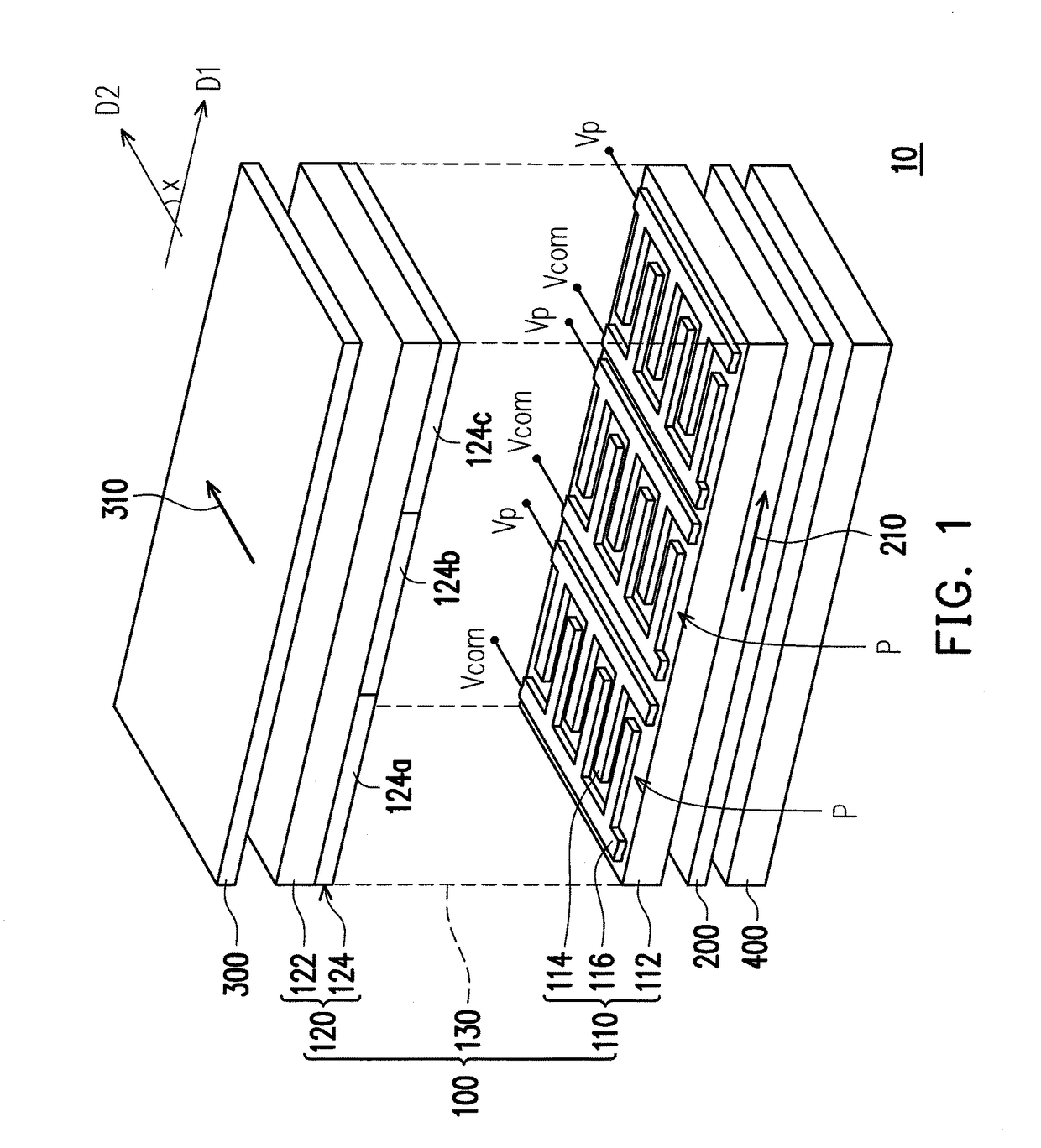
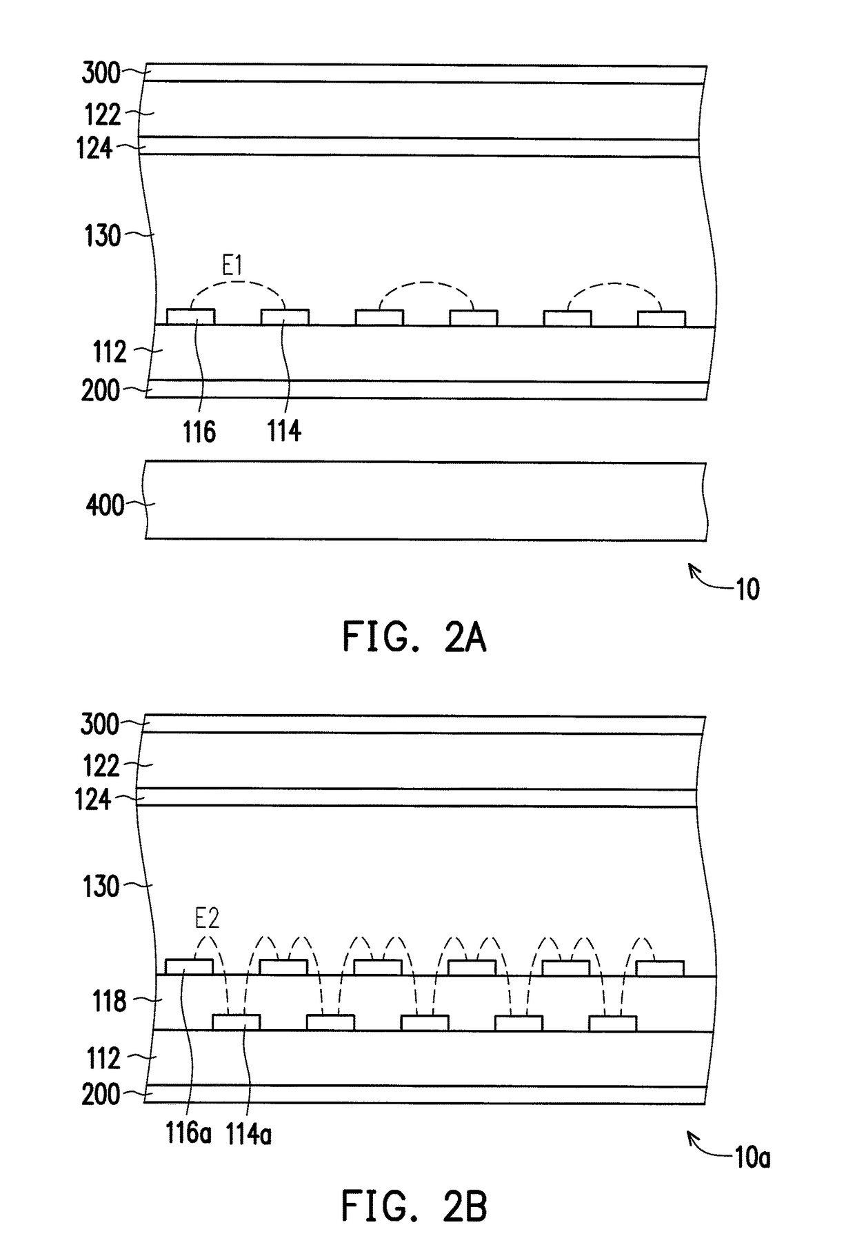
[0032]FIG. 1 is a three-dimensional schematic diagram of a display apparatus according to an embodiment of the invention. FIG. 2A is a partial cross-sectional schematic diagram of the display apparatus depicted in FIG. 1. Referring to FIG. 1 and FIG. 2A, a display apparatus 10 of the present embodiment includes a display panel 100, a first polarizer 200, a second polarizer 300 and a light source module 400. The light source module 400 is disposed at one side of the display panel 100, and an incident light is provided by the light source module 400 to the display panel 100. The display panel 100 includes a pixel array substrate 110, an opposite substrate 120 and a display medium 130.

[0033]The pixel array substrate 110 includes a plurality of pixel units P. The pixel units P are disposed on a first substrate 112 in an array. Each of the pixel units P includes a first electrode 114 and a second electrode 116. The first electrode 114 and the second electrode 116 are alternately disposed...

second embodiment

[0056]FIG. 9 is a three-dimensional schematic diagram of a display apparatus according to an embodiment of the invention. Referring to FIG. 9 and FIG. 1 together, a display apparatus 20 of FIG. 9 is similar to the display apparatus 10 of FIG. 1, thus elements identical to that of FIG. 1 are indicated by the same reference numbers, and the descriptions thereof are not repeated. A difference between the display apparatus 20 of FIG. 9 and the display apparatus 10 of FIG. 1 is that, the display apparatus 20 of FIG. 9 further includes a biaxial compensation film 500 disposed between the display panel 100 and the second polarizer 300. In addition, detailed structure of each component in the display panel 100 is not illustrated in FIG. 9.

[0057]Generally, the biaxial compensation film is mainly used to increase a viewing angle. In the present embodiment, the biaxial compensation film 500 has a third optical axis 510 and the third optical axis 510 is parallel to a third direction D3. As show...

third embodiment

[0064]FIG. 12A is a three-dimensional schematic view of a display apparatus according to an embodiment of the invention. Referring to FIG. 12A and FIG. 1 together, a display apparatus 30 of FIG. 12A is similar to the display apparatus 10 of FIG. 1, thus elements identical to that of FIG. 1 are indicated by the same reference numbers, and the descriptions thereof are not repeated. In addition, detailed structure of each component in the display panel 100 is not illustrated in FIG. 12A.

[0065]More specifically, a difference between the display apparatus 30 of FIG. 12A and the display apparatus 10 of FIG. 1 is that, a second polarizer 600 of FIG. 12A has a second optical axis 610 in which the second optical axis 610 is parallel to a fourth direction D4, and an included angle z between the second optical axis 610 and the first optical axis 210 is 90°. The display apparatus 30 of FIG. 12A further includes a first positive A-plate compensation film 700A, a second positive A-plate compensat...


PUM

PropertyMeasurementUnit
included angleaaaaaaaaaa

Abstract

A display apparatus including a display panel, a first polarizer and a second polarizer is provided. The display panel includes a pixel array substrate, an opposite substrate and a display medium. The pixel array substrate includes a plurality of pixel units. Each pixel unit includes a first electrode and a second electrode. The first electrode and the second electrode are alternately arranged and a lateral electric field is existed between the first electrode and the second electrode. The opposite substrate is disposed opposite to the pixel array substrate. The display medium is disposed between the pixel array substrate and the opposite substrate. The first polarizer is disposed on the pixel array substrate. The second polarizer is disposed on the opposite substrate. An included angle between an optical axis of the first polarizer and an optical axis of the second polarizer is 90°±θ, and θ is 1° to 9°.

Description

CROSS-REFERENCE TO RELATED APPLICATION[0001]This application claims the priority benefits of U.S. provisional application Ser. No. 61 / 806,411, filed on Mar. 29, 2013. The entirety of the above-mentioned patent applications is hereby incorporated by reference herein and made a part of this specification.BACKGROUND OF THE INVENTION[0002]Technical Field[0003]The invention of the disclosure generally relates to a display apparatus, and more particularly to a display apparatus having polarizers being disposed non-orthogonally.[0004]Description of Related Art[0005]In response to consumers demand, manufacturers of display apparatus industry have invested in development of a blue phase liquid crystal display apparatus having quick response characteristic. Taking a blue phase liquid crystal material for example, a lateral electric field is required so the blue phase liquid crystal material can be operated as a light valve. An electrode design with a In-Plane Switching (IPS) display module ha...

Claims


Application Information

Patent Timeline
Patent Type & Authority Patents(United States)
IPC IPC(8): G02F1/1335G02F1/13363G02F1/1343G02F1/139G02F1/137
CPCG02F1/133528G02F1/13363G02F1/134363G02F1/1396G02F2001/13793G02F2001/133531G02F2001/134372G02F2413/01G02F2413/02G02F2413/03G02F2413/12G02F1/133531G02F1/134372G02F1/13793
Inventor LIU, YI-FANWU, SHIN-TSONLAN, YI-FENTSAI, CHENG-YEH
Owner AU OPTRONICS CORP
Why Eureka
Try Eureka