Magnetic recording device and magnetic recording method

Active Publication Date: 2017-05-30
TDK CORPARATION
View PDF3 Cites 14 Cited by
  • Summary
  • Abstract
  • Description
  • Claims
  • Application Information

AI Technical Summary

Benefits of technology

[0080]In the microwave assisted magnetic head 1 in this embodiment, magnetic flux generated as a result of a recording current being supplied from the recording current supply part 91a to the first coil 9a and second coil 9b is guided by the main magnetic pole layer 6 to the magnetic recording layer (perpendicular magnetization layer) of the magnetic disc 100 to write on while converging, whereby a recording magnetic field emerges from the end face 61a on the ABS 70 side of the main magnetic pole layer 6 (main magnetic pole part 61).
[0081]Concurrently, a drive current (direct current) IOP supplied from the drive current supply part 91b flows through the main magnetic pole layer 6 (main magnetic pole part 61), spin torque oscillator 10, and trailing shield 7 in this order. As the drive current IOP flows, magnetization of the spin injection layer 12 causes electrons to be spin-polarized. When the spin polarization rate of the spin injection layer 12 is positive, the spin electrons polarized in the opposite direction to the majority spin of the spin injection layer 12 are reflected on the spin injection layer and injected into the magnetic field generation layer 14. The reflected spin electrons act on the magnetization of the magnetic field generation layer 14 and induce magnetization precession of the magnetic field generation layer 14, whereby a microwave magnetic field is generated from the magnetic field generation layer 14. With this microwave magnetic field being superimposed on the recording magnetic field from the main magnetic pole layer 6, signals can be recorded on the magnetic disc 100 having a high magnetic anisotropy energy Ku.
[0082]Here, if a microwave magnetic field is constantly generated while signals are recorded, the problem that the microwave magnetic field assists the returning magnetic field that is the recording magnetic field returning to the trailing shield 7 (the magnetic field in the opposite direction to the recording magnetic field) and lowers the quality of signals recorded on the magnetic disc 100 (see the pri

Problems solved by technology

However, as the magnetic grains become smaller, the magnetic grains are less thermally stable in association with their reduced volume.
Therefore, if the anisotropic magnetic field of a magnetic recording medium exceeds an acceptable value determined based on the upper limit of the recording magnetic field intensity, recording on the magnetic recording medium fails.
There is a problem that the writing operation according to a recording current of a relatively long polarity re

Method used


Image

  • Magnetic recording device and magnetic recording method
  • Magnetic recording device and magnetic recording method
  • Magnetic recording device and magnetic recording method

Examples


example 1

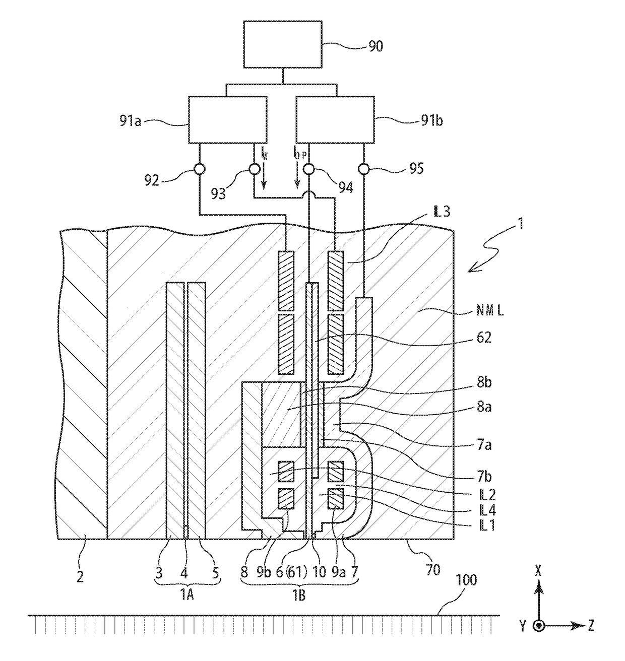
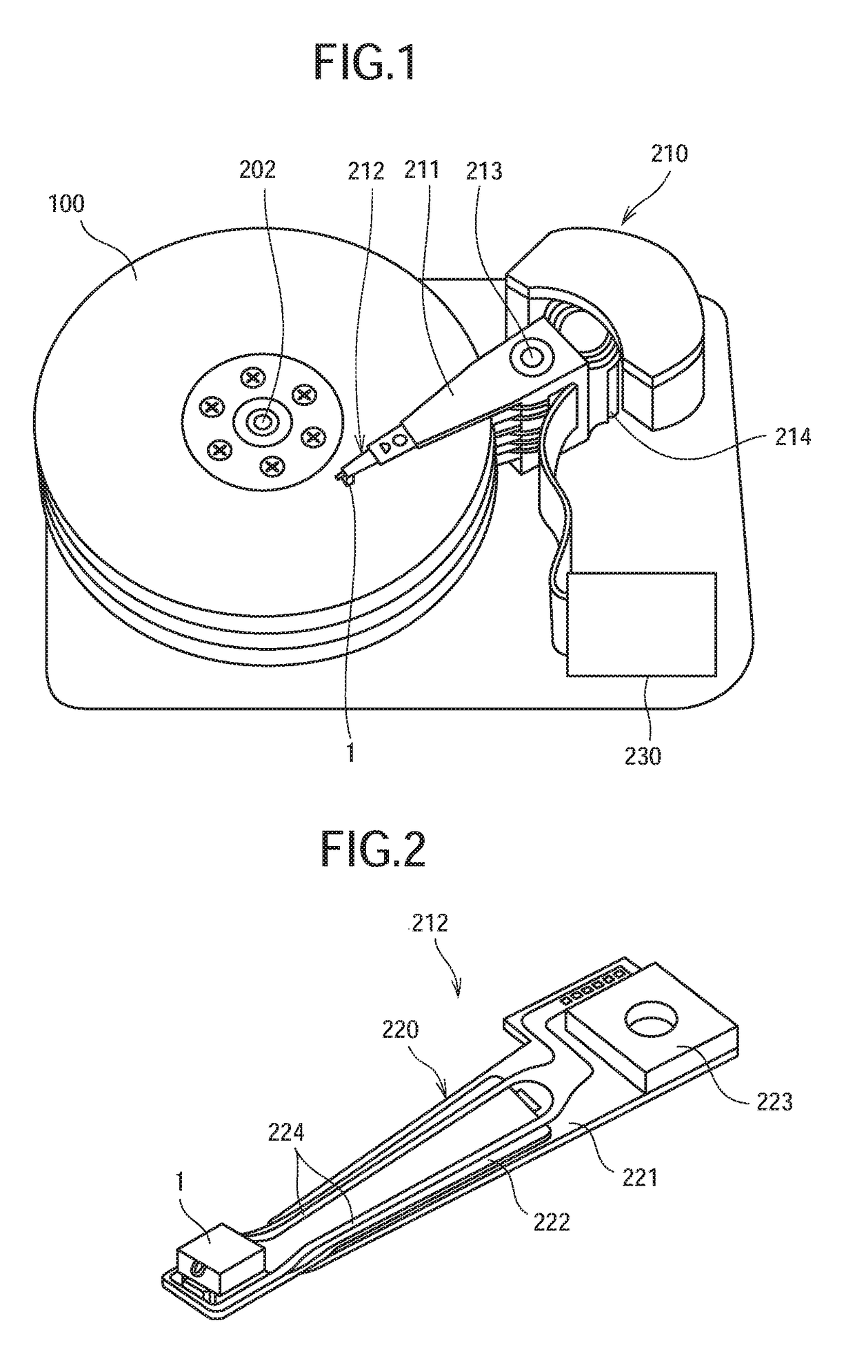
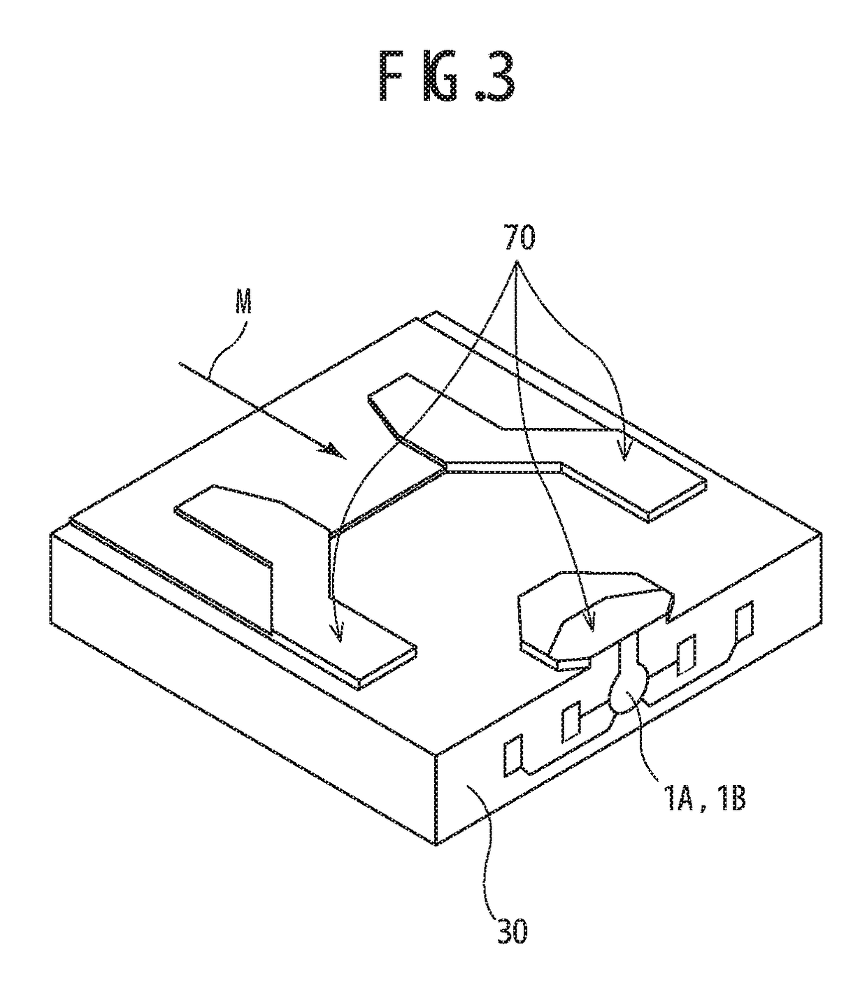
[0109]Using the magnetic recording device having the configuration shown in FIGS. 1 to 9, signals were recorded on a magnetic disc, the signals were read with the reproducing head 1A of the microwave assisted head 1, and the SN ratios (dB) of the reproduced signals were measured. The results are shown in FIG. 13.

[0110]Here, upon recording signals, the recording current waveform data DWW as shown in FIG. 10A were created based on the signals to record, the unit drive current waveforms UOP were created as shown in FIGS. 11A and 11B, and the drive current waveform data DOPW as shown in FIG. 10B were created. The signals recorded on a magnetic disc included a signal S1 corresponding to a relatively short polarity reversal interval GPR1, a signal S3 corresponding to a relatively long polarity reversal interval GPR3, and a signal S2 corresponding to a polarity reversal interval GPR2 in-between. The relationship between the threshold time TH for creating the drive current waveform data DOP...

reference example 1

[0113]Signals were recorded on a magnetic disc in the same manner as in Example 1 except that no drive current IOP was applied while recording the signals. The signals were read with the reproducing head 1A of the microwave assisted head 1, and the SN ratios (dB) of the reproduced signals were measured. The results are shown in FIG. 13.

[0114]FIG. 13 is a graph showing the SN ratios (dB) of the signals S1 to S3. The results shown in FIG. 13 confirmed that it is possible to improve the SN ratio of the signal S1 corresponding to a relatively short polarity reversal interval GPR and prevent deterioration in quality of the signal S3 corresponding to a relatively long polarity reversal interval GPR3 by controlling supply of the drive current IOP according to the length of the polarity reversal interval GPR in the recording current waveform data DWW based on the signals to be recorded as in Example 1.


PUM


Abstract

A magnetic recording device includes a magnetic recording medium, a microwave assisted magnetic head having a main magnetic pole for generating a recording magnetic field, and a spin torque oscillator provided near the main magnetic pole for generating a microwave magnetic field, a recording current supply part for supplying a recording current to recording coils according to recording current waveform data, a drive current supply part for supplying a drive current to the spin torque oscillator, and a drive current control part for controlling supply of the drive current by the drive current supply part based on the data. Taking into consideration as an indicator whether a polarity reversal interval included in the data exceeds a threshold time, the drive current control part controls the drive current supply part so as not to substantially lower the quality of signals recorded on the magnetic recording medium.

Description

FIELD OF THE INVENTION[0001]The present invention relates to a magnetic recording device having a microwave assisted magnetic head, and a magnetic recording method.BACKGROUND OF THE INVENTION[0002]In the field of magnetic recording using a head and a medium, further improvement in performance of the magnetic recording medium and the magnetic head is demanded as the recording density of magnetic disc devices increases.[0003]A magnetic recording medium is a discontinuous medium consisting of a set of magnetic grains. The magnetic grains each have a single-domain structure. Each recording bit on a magnetic recording medium consists of a plurality of magnetic grains. Therefore, in order to increase the recording density, the magnetic grains must be smaller and the borders between adjacent recording bits must be less uneven. However, as the magnetic grains become smaller, the magnetic grains are less thermally stable in association with their reduced volume.[0004]A presumable measure to ...

Claims


Application Information

Patent Timeline
IPC IPC(8): G11B27/36G11B5/17G11B5/09G11B5/39G11B5/00
CPCG11B5/3909G11B5/09G11B5/17G11B2005/0024G11B5/02G11B5/235G11B5/3123G11B5/3146
Inventor KOBAYASHI, TATSUHIROYONEDA, SADAHARUAOYAMA, TSUTOMU
Owner TDK CORPARATION
Why Eureka
Try Eureka