Microwave-assisted magnetic recording head and magnetic read/write apparatus using the same

a technology of microwave-assisted magnetic recording and magnetic read/write, which is applied in the direction data recording, instruments, etc., can solve the problems of difficult to provide a high recording density of 1 tb/in, the inability to independently control the microwave magnetic field strength, frequency, and recording magnetic field strength after manufacture of magnetic recording heads, etc., to prevent the deformation of the recording density, improve the recording density, and improve the effect of snr

Inactive Publication Date: 2011-09-08
HITACHI LTD
View PDF6 Cites 49 Cited by
  • Summary
  • Abstract
  • Description
  • Claims
  • Application Information

AI Technical Summary

Benefits of technology

[0029]An aspect of the present invention can provide a magnetic recording head mounted with a microwave oscillator capable of recording high-density patterns at an excellent SNR on a magnetic recording medium having high magnetic anisotropy energy. The invention can also provide a magnetic read / write apparatus including such magnetic recording head.
[0030]According to another aspect of the invention, the magnetic recording head mounted with the microwave oscillator provides the feature that can appropriately control relative positions for the main magnetic pole and the microwave oscillator of the magnetic recording head. It is possible to prevent the recording density from degrading due to manufacturing errors in the magnetic recording head and ensure high recording density.

Problems solved by technology

The technologies disclosed in patent documents 1 and 2 and non-patent document 1 make it difficult to provide a high recording density of 1 Tb / in2 because the oscillated microwave magnetic field provides too low a frequency or too weak a magnetic field strength.
It is impossible to independently control the microwave magnetic field strength, the frequency, and the recording magnetic field strength after manufacture of magnetic recording heads.

Method used


Image

  • Microwave-assisted magnetic recording head and magnetic read/write apparatus using the same
  • Microwave-assisted magnetic recording head and magnetic read/write apparatus using the same
  • Microwave-assisted magnetic recording head and magnetic read/write apparatus using the same

Examples


first embodiment

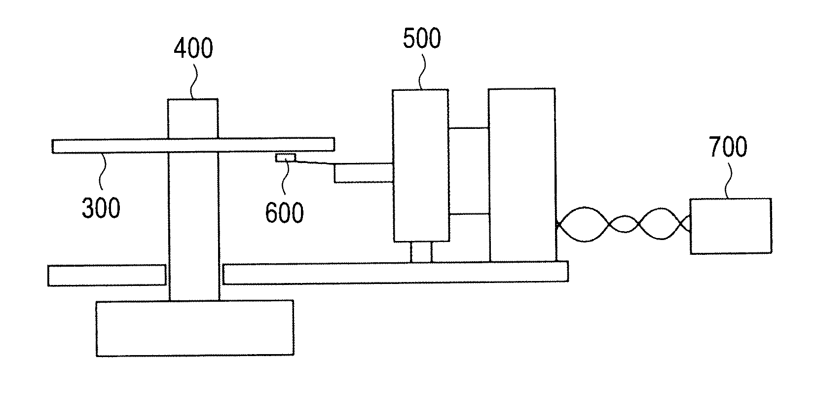
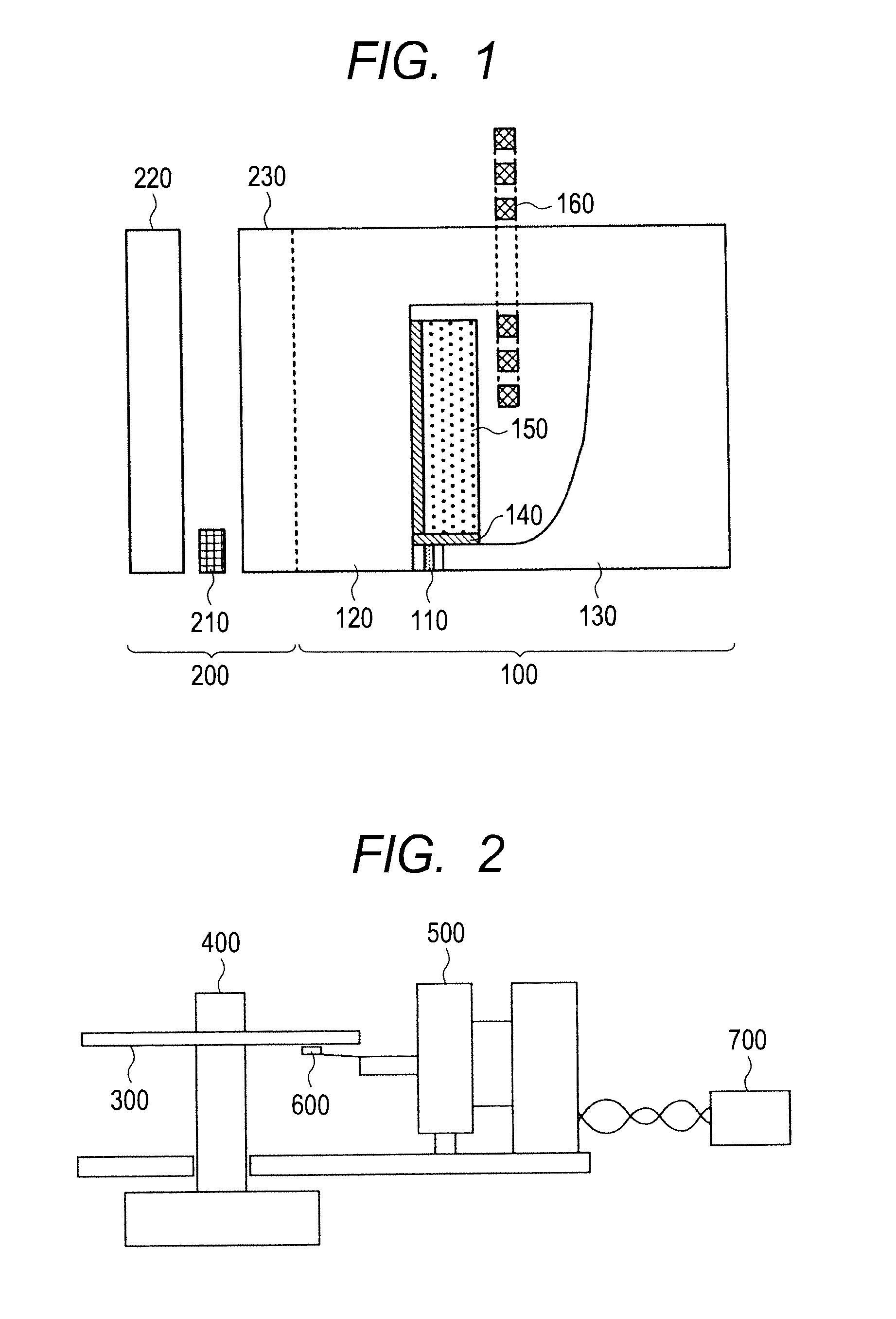
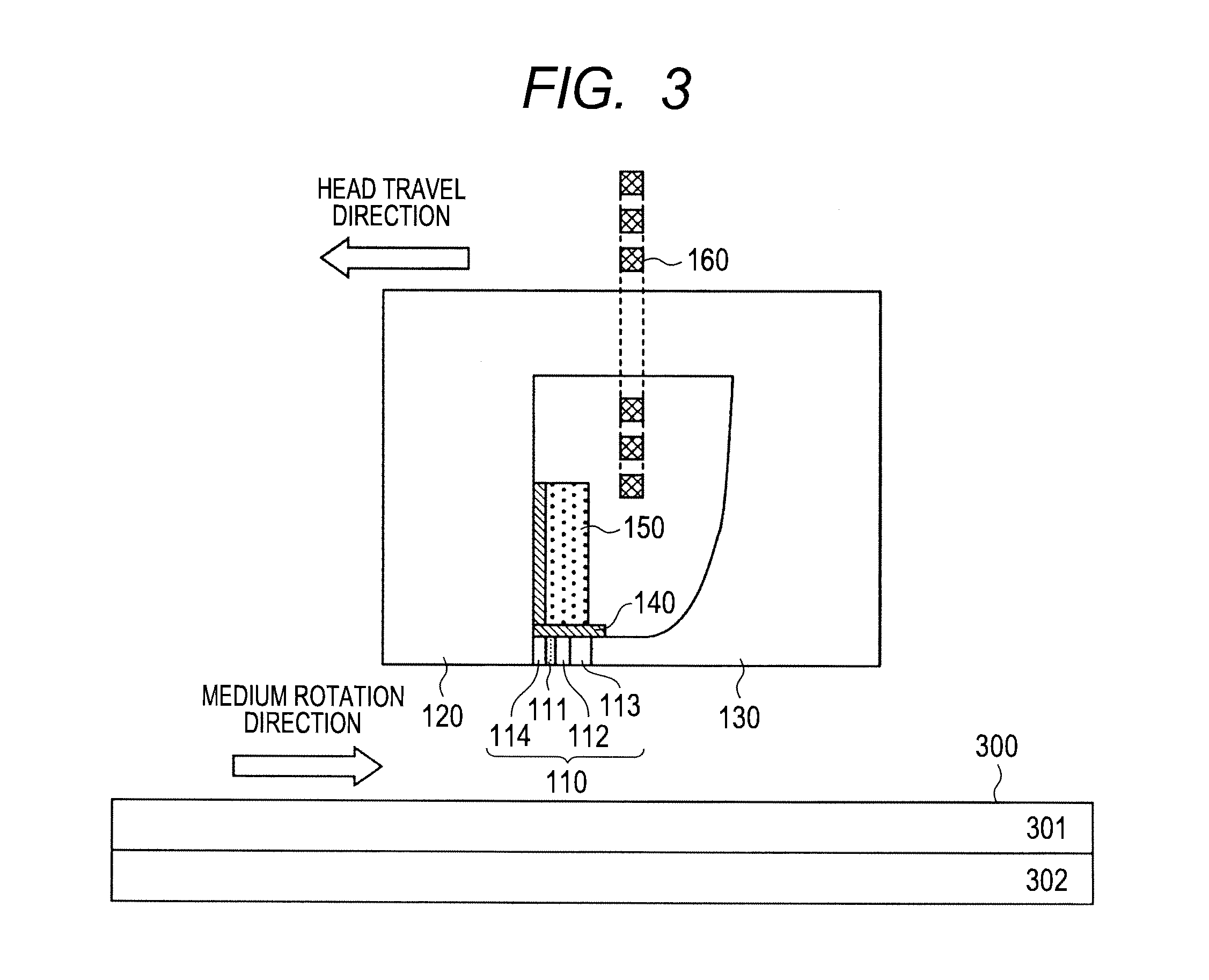
[0047]FIG. 1 shows a schematic diagram of a magnetic read / write head as part of a configuration example of the magnetic read / write apparatus according to the invention. The magnetic read / write head is separated for reading and writing and includes a recording head section 100 and a read head section 200. The recording head section 100 includes an oscillator 110, a main magnetic pole 120, a shield 130, a first thermal expansion device 150, an insulation layer 140, and a coil 160. The oscillator 110 generates a microwave magnetic field. The main magnetic pole 120 generates a recording head magnetic field. The shield 130 controls the magnetization rotation direction of the oscillator 110. The first thermal expansion device 150 adjusts the position of the oscillator toward a magnetic recording medium. The insulation layer 140 insulates the oscillator 110 from the first thermal expansion device 150. The coil 160 excites the main magnetic pole to generate a magnetic field. The feature of ...

second embodiment

[0067]The second embodiment of the invention will be described. The embodiment differs from the first embodiment only in the configuration of the recording head section 100. The following omits the description about duplicate part of the magnetic read / write apparatus according to the first embodiment other than the recording head section 100. FIG. 10 illustrates an enlarged view of the recording head section 100 according to the embodiment. FIG. 10 assumes that no power is applied to the first thermal expansion device 150 or the third thermal expansion device. A feature of the embodiment is that the bottom face of the oscillator 110 is higher than that of the main magnetic pole 120 in the device height direction. The embodiment specifies a relative distance of 4 nm between the oscillator 110 and the main magnetic pole 120 when no power is applied to the first thermal expansion device 150. In FIG. 10, the shield 130 is at the same level as the oscillator 110 but may be at the same le...

third embodiment

[0072]The third embodiment of the invention will be described. The embodiment differs from the first embodiment only in the configuration of the recording head section 100. The following omits the description about duplicate part of the magnetic read / write apparatus according to the first embodiment other than the recording head section 100. FIG. 12 illustrates an enlarged view of the recording head section 100 according to the embodiment. According to the configuration of the first embodiment, the thermal expansion device 150 is positioned over the oscillator. According to the configuration of the third embodiment, a second thermal expansion device 154 is provided to the rear of the shield 130 viewed from the oscillator 110. An insulation layer 141 is provided between the second thermal expansion device 154 and the shield 130. FIG. 12 assumes that no power is applied to the second thermal expansion device 154. According to the configuration of the first or second embodiment, the ro...


PUM

PropertyMeasurementUnit
thicknessaaaaaaaaaa
oscillation frequencyaaaaaaaaaa

Abstract

A microwave-assisted magnetic recording head includes: a main magnetic pole that generates a recording magnetic field to be recorded on a magnetic recording medium; a shield; and an oscillator that is provided between the main magnetic pole and the shield and generates a microwave magnetic field. The microwave-assisted magnetic recording head is provided with a thermal expansion device for adjusting a relative position between the oscillator and the main magnetic pole so as to be able to independently adjust a recording magnetic field from the main magnetic pole and a microwave magnetic field from the oscillator.

Description

CLAIM OF PRIORITY[0001]The present application claims priority from Japanese patent application JP2010-48120 filed on Mar. 4, 2010, the content of which is hereby incorporated by reference into this application.BACKGROUND OF THE INVENTION[0002]1. Field of the Invention[0003]The present invention relates to a magnetic recording head having a function of inducing magnetization reversal by applying a microwave magnetic field to a magnetic recording medium and relates to a magnetic read / write apparatus using the magnetic recording head.[0004]2. Description of the Related Art[0005]Recently, a recording density on magnetic read / write apparatuses such as HDDs (Hard Disk Drives) is requested to increase as fast as 40% per year. The surface recording density is expected to become one Tbit / in2 by the year 2012. Improvement of the surface recording density requires miniaturizing magnetic write and read heads and reducing particle sizes for magnetic recording media. However, miniaturizing a mag...

Claims


Application Information

Patent Timeline
Patent Type & Authority Applications(United States)
IPC IPC(8): G11B5/02
CPCG11B5/02G11B2005/0024G11B5/314G11B5/1278G11B5/3146G11B5/3133G11B5/3116
Inventor SHIIMOTO, MASATOIGARASHI, MASAKAZUFURUKAWA, MASARU
Owner HITACHI LTD
Why Eureka
Try Eureka