
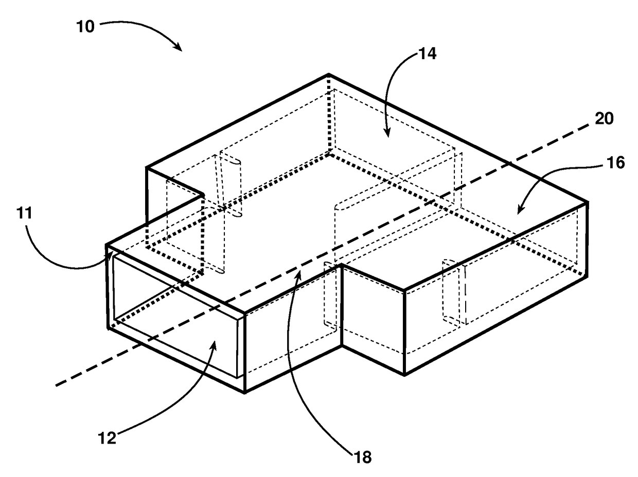
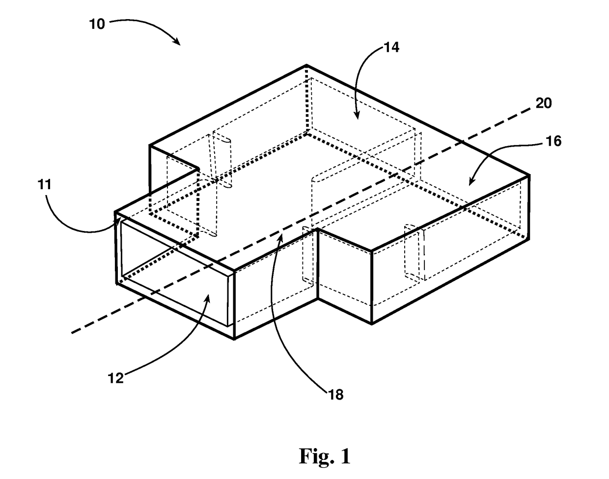
Compact folded Y-junction waveguide

a waveguide and compact technology, applied in the field of rf power distribution devices, can solve the problems of large signal error, inability to meet the requirements of many aerospace applications, and limited frequency bandwidth of existing rf waveguide power distribution devices, and achieve the effect of low signal error and high bandwidth

Active Publication Date: 2017-05-30
THE UNITED STATES OF AMERICA AS REPRESETNED BY THE SEC OF THE AIR FORCE
View PDF5 Cites 1 Cited by
  • Summary
  • Abstract
  • Description
  • Claims
  • Application Information

AI Technical Summary

Benefits of technology

The present invention provides a compact waveguide with high bandwidth and low signal error. It includes a conductive body with a common junction and a septum. The septum and iris elements change the impedance of the common junction to match the impedance across the entire waveguide bandwidth. This results in a uniform impedance across the entire waveguide, which reduces signal error and improves the quality of the signal transmission.

Problems solved by technology

Unfortunately, the existing art of RF waveguide power distribution devices have very limited frequency bandwidth, generate unacceptable amplitude and phase errors, and can be too large for many aerospace applications.

Method used


Image

  • Compact folded Y-junction waveguide
  • Compact folded Y-junction waveguide
  • Compact folded Y-junction waveguide

Examples


Embodiment Construction

[0017]As a preliminary matter, embodiments of the disclosed invention may operate in either a power combining or dividing mode of a waveguide distribution network. Thus, in one exemplary embodiment, the distribution network, or waveguide combiner / divider, is considered to be a passive reciprocal structure. A reciprocal network may be defined as one in which the power losses are the same between any two ports regardless of the direction of propagation. Therefore, for sake of clarity in discussing the embodiments that follow, the examples disclosed herein are generally discussed from a power divider perspective. Stated another way, examples discussed herein are generally with reference to a single signal that is distributed as described herein from an input port (or waveguide portions) a to two or more outputs (N≧2) (waveguide portions). Nevertheless, the use of such language to identify the components of the device is not intended to limit the scope of the description of the inventio...


PUM


Abstract

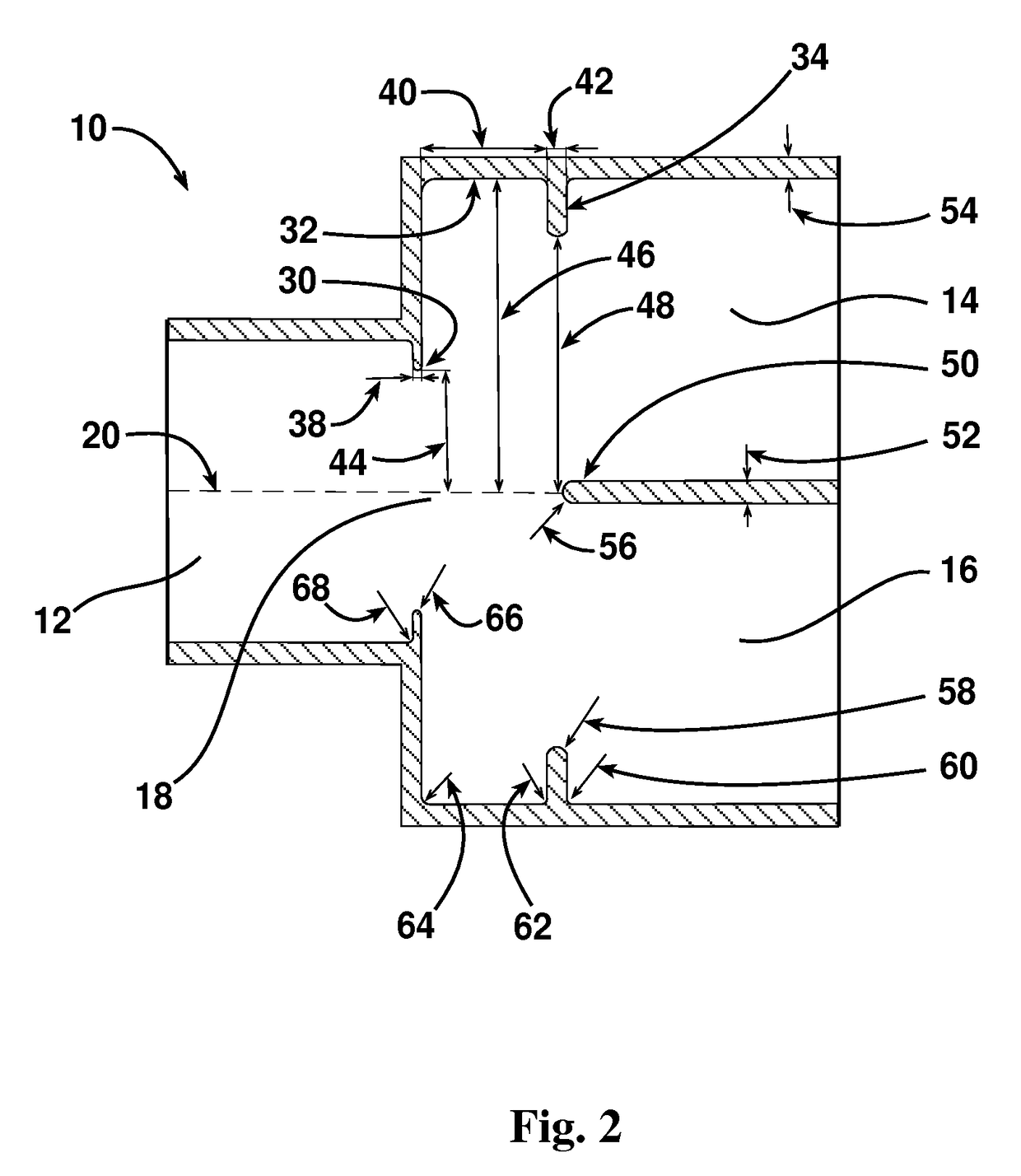
A high bandwidth, low signal error, compact waveguide includes a conductive body including a waveguide input portion and a plurality of waveguide output portions disposed coplanar with the input waveguide portion. The waveguide further includes a common junction joining the input waveguide portion and the plurality of output waveguide portions. A septum is disposed proximate the common junction collinear with a centerline of the input waveguide portion. The waveguide further includes a plurality of iris elements disposed proximate the common junction transverse to the centerline of the input waveguide portion. The septum and the plurality of iris elements changes an impedance of the common junction to match the impedance across the entire waveguide bandwidth.

Description

RIGHTS OF THE GOVERNMENT[0001]The invention described herein may be manufactured and used by or for the Government of the United States for all governmental purposes without the payment of any royalty.FIELD OF THE INVENTION[0002]The present disclosure relates generally to RF power distribution apparatus, and specifically to combiners or dividers in radio frequency (RF) systems for radar and communication applications.BACKGROUND OF THE INVENTION[0003]Radio frequency (RF) and microwave circuits and systems typically require power distribution networks to divide an RF input signal at a single input into N quantity RF output signals at N outputs, where N may be defined as any regular number of powers two (N=2, 4, 8, 16, 32, . . . ). Likewise, the power distribution networks can also be used to combine N quantity RF input signals at N inputs into a single RF output signal at a single output. For antenna arrays, the RF power distribution network size is constrained by the antenna feed and...

Claims


Application Information

Patent Timeline
Patent Type & Authority Patents(United States)
IPC IPC(8): H01P5/12H01P3/12H01P5/19
CPCH01P3/12H01P5/19H01P5/12
Inventor MASSMAN, JEFFREY P.
Owner THE UNITED STATES OF AMERICA AS REPRESETNED BY THE SEC OF THE AIR FORCE
Learn More