
Vehicle or trailer with dropping floor

a technology of loading bed and floor, which is applied in the direction of loading transportation vehicles, transportation items, vehicles with tipping movement, etc., can solve the problems of high requirements for the unloading mechanism, large unloading mechanism requirements, and large volume of unloading and unloading, so as to reduce the volume loading capacity and/or the weight loading capacity of the loading bed, the effect of maximising the load carrying capacity and/or ease of loading and unloading

Inactive Publication Date: 2017-06-06
AVELING BARFORD HLDG
View PDF20 Cites 0 Cited by
  • Summary
  • Abstract
  • Description
  • Claims
  • Application Information

AI Technical Summary

Benefits of technology

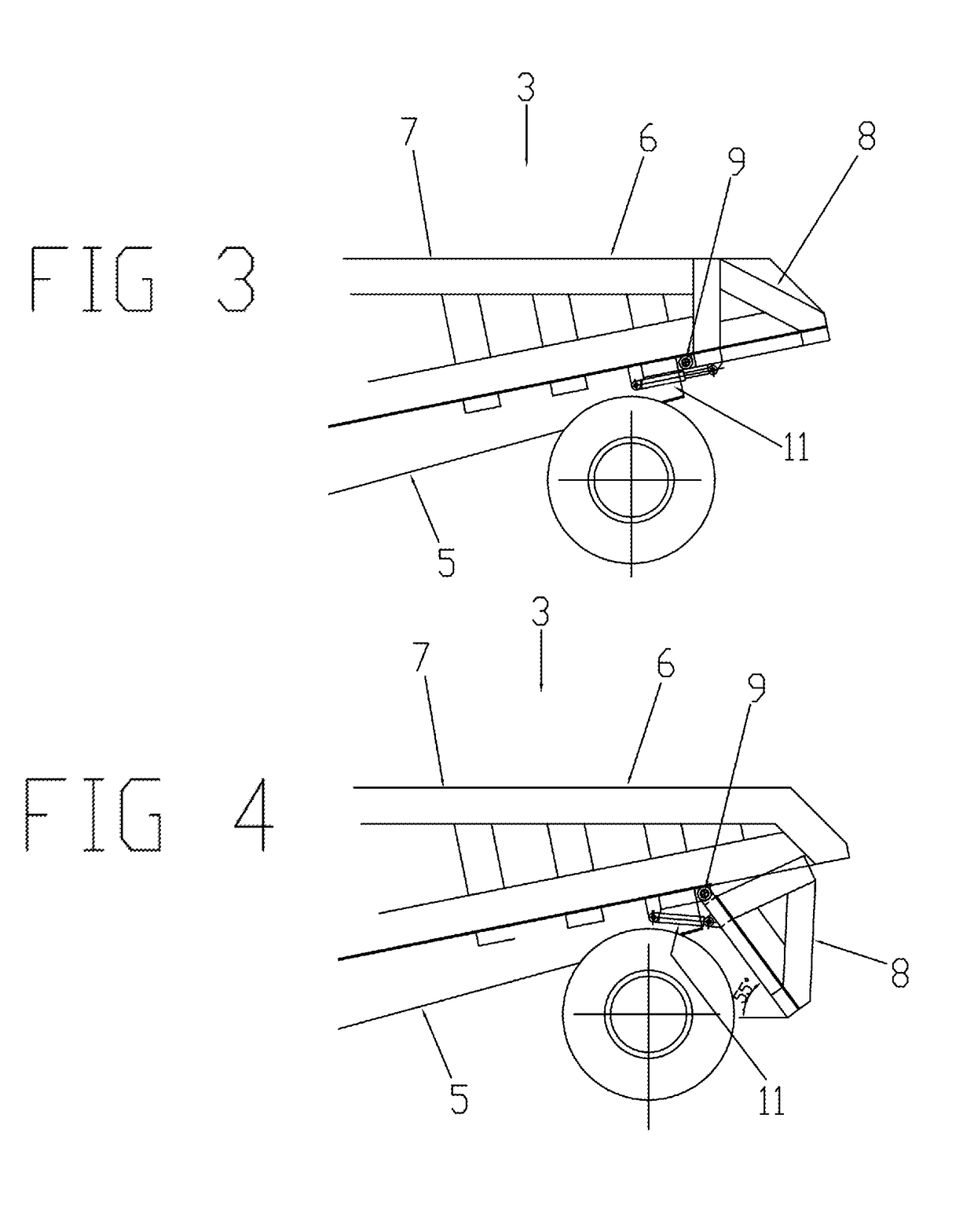
[0009]By pivotally moving the second body section relative to the first body section from its first position to its second position, the invention allows the volume loading capacity and / or the weight loading capacity of the loading bed to be varied. The loading bed may therefore discharge a portion of a load which it carries by moving the second body section relative to the first body section. A portion of the load carried by the loading bed may therefore be discharged before or during actuation of a main unloading mechanism (for example a tipper or ejector type unloading mechanism) which discharges the remainder of the load.
[0010]In this way the invention reduces loading requirements for the main unloading mechanism. The weight, complexity and cost of the main unloading mechanism may therefore be reduced. The invention may also reduce power requirements for operating the main unloading mechanism and allow the use of smaller actuators, thereby reducing the cost and weight of the loading bed. The rate at which the loading bed can discharge its load may also be increased.
[0011]The side walls of the second body section may reduce or substantially prevent spillage of a load being discharged from the loading bed over the side edges of the second body section. The side walls may reduce or prevent lateral spilling of load both as the second body section is moving from the first position towards the second position to discharge a portion of the load and as the main unloading mechanism is operating to discharge the remainder or a further portion of the load while the second body section is in its second position. Therefore the load may be deposited more accurately.
[0031]The base of the second body section may be substantially co-planar with the base of the first body section when the second body section is in the first position. The bases of the first and second body sections may therefore combine to form a substantially continuous planar base of the loading bed. The base of the loading bed may be substantially planar substantially along its length when the second body section is in the first position. Alternatively the base of the second body section may be at an angle to the base of the first body section when the second body section is in the first position. For example, the base of the second body section may be pivotally raised above the base of the first body section when the second body section is in the first position. The angle of the second body section relative to the first body section may be selected to maximise load carrying capacity and / or ease of loading and unloading.
[0032]The volume loading capacity and / or the weight loading capacity of the loading bed may be substantially reduced when the second body section moves from the first position to the second position.

Problems solved by technology

However, the desire to maximise load carrying capacity may lead to high requirements for the unloading mechanism.
For example, the unloading mechanism may require large, heavy and expensive actuators, and may require a significant amount of power to discharge the load from the loading bed.

Method used


Image

  • Vehicle or trailer with dropping floor
  • Vehicle or trailer with dropping floor
  • Vehicle or trailer with dropping floor

Examples


Embodiment Construction

)

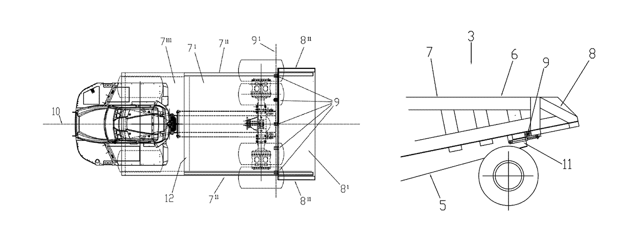
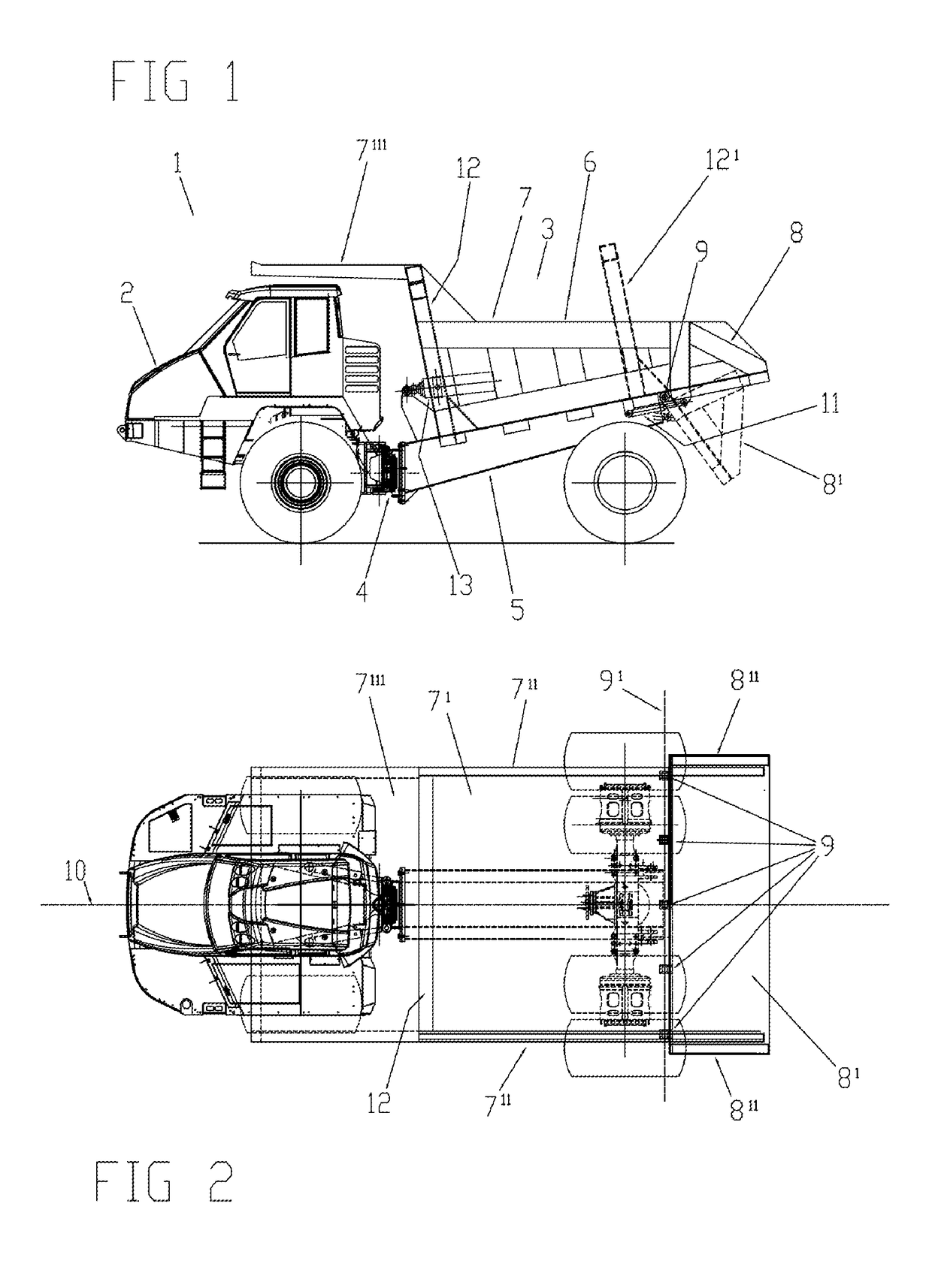
[0050]FIGS. 1 and 2 illustrate side and top views respectively of an ADT 1 having a front tractor 2 and a rear wagon 3. The rear wagon 3 may be permanently connected to the front tractor 2 or alternatively may be a detachable rear wagon or trailer which may be decoupled and separated from the front tractor allowing subsequent reattachment of the same rear wagon or attachment of a different rear wagon to the front tractor. The ADT 1 uses articulated steering, and has a pair of rams (not shown) which are used to pivot the front tractor 2 relative to the rear wagon to effect steering. The ADT 1 is for transporting and discharging loads, for example rubble, earth, hard-core, building materials or any type of construction, waste or industrial material, and may generally be used to transport any kind of load.

[0051]The front tractor 2 is a single axle drive unit comprising a cab from which an operator may control the ADT. The rear wagon 3 is connected to the front tractor at a pivot mecha...


PUM


Abstract

A loading bed for a load carrying vehicle or trailer, the loading bed having a base and including first and second body sections and an ejector type unloading mechanism, wherein the first body section has a base and a pair of opposing side walls, wherein the second body section has a base and a pair of opposing side walls, wherein the bases of the first and second body sections form at least a portion of the base of the loading bed, wherein the second body section is pivotably movable relative to the first body section between a first position and a second position, wherein the second body section is adapted to pivot relative to the first body section while the first body section remains fixed relative to a vehicle or trailer to which the loading bed is attached.

Description

CROSS REFERENCE TO RELATED APPLICATIONS[0001]This application is a U.S. national stage of International Application No. PCT / GB2013 / 053200, filed Dec. 3, 2012, which claims priority to GB Application No. 1221797.2 filed on Dec. 4, 2012, both of which are incorporated herein in their entireties.FIELD OF THE INVENTION[0002]The invention relates to a loading bed for a load carrying vehicle or trailer, and to a vehicle or trailer having a loading bed.BACKGROUND OF THE INVENTION[0003]A load carrying vehicle or a trailer for a vehicle, for example an articulated dump truck (ADT), may have a loading bed for carrying a load. The loading bed may have an unloading mechanism for discharging a load carried by the loading bed. For example, the loading bed may have a tipper mechanism which lifts one end of the loading bed to pivot the loading bed about a pivot axis, thereby causing the load or a portion of the load to be tipped out of the loading bed. Alternatively, an ejector mechanism may sweep ...

Claims


Application Information

Patent Timeline
Patent Type & Authority Patents(United States)
IPC IPC(8): B60P1/26B60P1/56B60P1/28
CPCB60P1/56B60P1/26B60P1/283B60P1/286B60P1/28B60P1/433B65F3/26B65F3/28
Inventor KEATING, ALANLLOYD, DAVID RODERICKTHOMSON, BRIAN
Owner AVELING BARFORD HLDG
Learn More