Flexible fastening system

a flexible and implant-type technology, applied in the field of implants, can solve the problems of ineffectiveness, wire pulling through the anatomy, damage to the pedicles, etc., and achieve the effect of reducing the force applied

Active Publication Date: 2017-06-13
K2M
View PDF41 Cites 22 Cited by
  • Summary
  • Abstract
  • Description
  • Claims
  • Application Information

AI Technical Summary

Benefits of technology

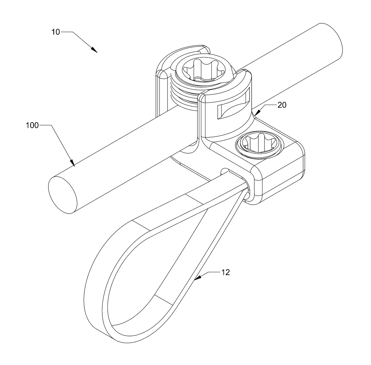
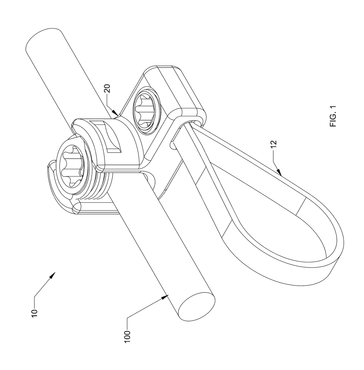
[0010]Accordingly, the present disclosure relates to a flexible implant system that has a flexible implant with a surface area larger than a surgical wire to distribute the load of the implant on a bony element thereby reducing forces applied to a specific point of the anatomy and is configured to provide fastening points for spinal rods as an alternative to screws and hooks.
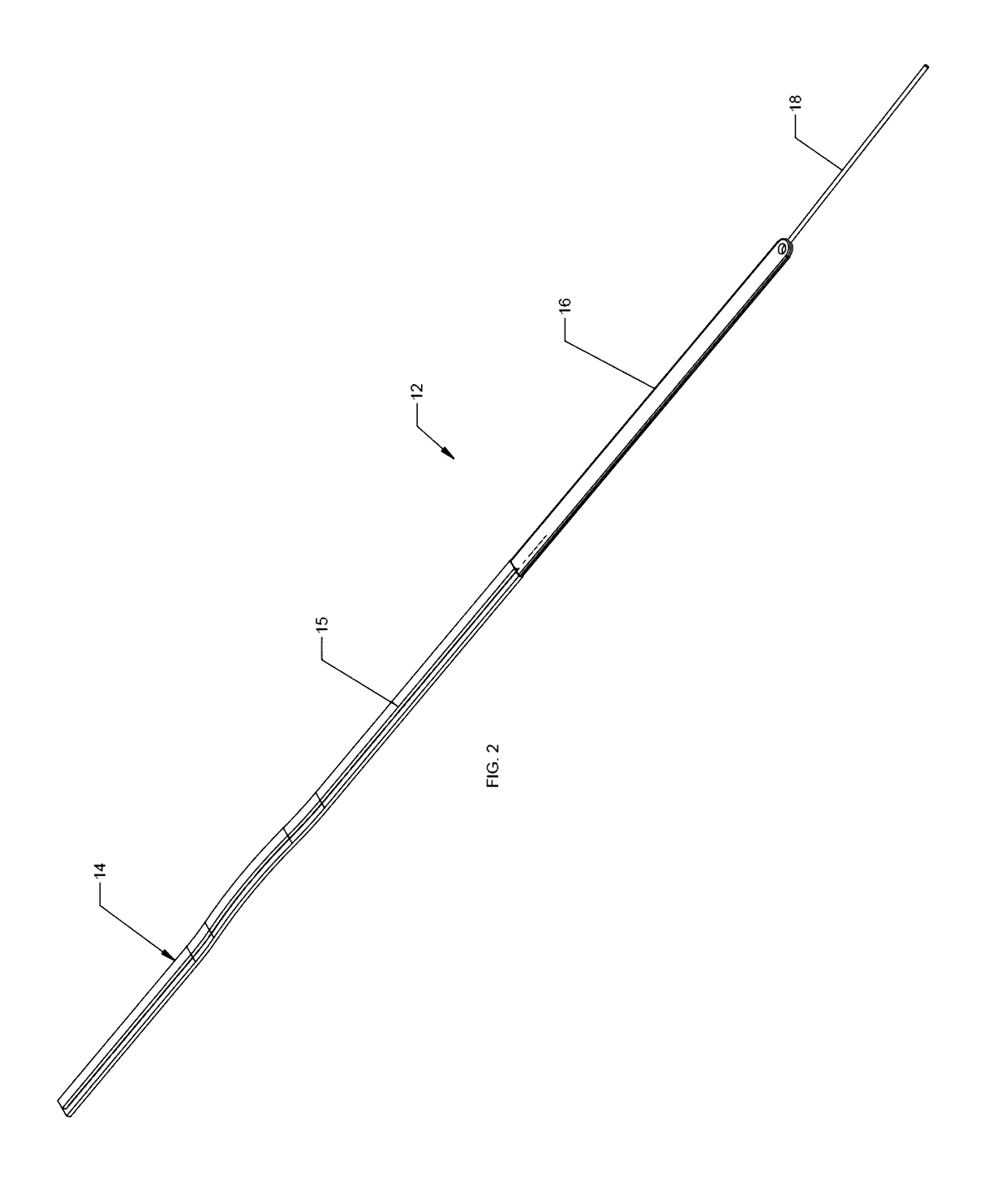
[0012]The flexible implant may include a leader coupled to an end of the flexible implant. The leader may be made of a malleable metal. The leader may be crimped to the flexible implant. The flexible implant may include a stiffening wire bonded to the flexible implant along a portion of the length of the flexible implant. The stiffening wire may increase the rigidity of the flexible implant. The stiffening wire may be internally bonded within the flexible implant along the entire length of the flexible implant.

Problems solved by technology

The screws are inserted into the pedicles of the vertebrae, and under certain circumstances, the pedicles may be damaged.
However, often due to the loading on the wire and the small surface area of the wire, the wire may pull through the anatomy and thus become ineffective.

Method used


Image

  • Flexible fastening system
  • Flexible fastening system
  • Flexible fastening system

Examples


Embodiment Construction

[0049]Embodiments of the present disclosure are now described in detail with reference to the drawings in which like reference numerals designate identical or corresponding elements in each of the several views. As used herein, the term “clinician” refers to a doctor, a nurse, or any other care provider and may include support personnel. Throughout this description, the term “proximal” will refer to the portion of the device or component thereof that is closest to the clinician and the term “distal” will refer to the portion of the device or component thereof that is farthest from the clinician. In addition, the term “cephalad” is used in this application to indicate a direction toward a patient's head, whereas the term “caudad” indicates a direction toward the patient's feet. Further still, for the purposes of this application, the term “lateral” indicates a direction toward a side of the body of the patient, i.e., away from the middle of the body of the patient. The term “posterio...


PUM


Abstract

A flexible implant system includes a flexible implant, an implant housing, and an implant set screw. The flexible implant is configured to loop around a portion of a bony element. The implant housing includes a housing body defining a rod passage configured to receive an rod. The housing body also defines an implant passage that receives a portion of the flexible implant. The implant set screw engages the flexible implant within the implant passage to fix the flexible implant to the implant housing.

Description

CROSS-REFERENCE TO RELATED APPLICATIONS[0001]The present application claims the benefit of, and priority to, U.S. Provisional Patent Application Ser. No. 61 / 775,739, filed on Mar. 11, 2013, the entire contents of which is incorporated herein by reference.BACKGROUND[0002]1. Technical Field[0003]The present disclosure relates to implants and, more specifically, to flexible implant systems for fastening an implant to a bony element.[0004]2. Discussion of Related Art[0005]The spine is made up of a superposition of vertebrae, that are normally aligned along a vertebral axis, extending from the lumbar vertebrae to the cervical vertebrae, with each vertebra presenting a posterior wall from which there projects a spinous process and two side edges having walls from which there project the ribs and / or transverse processes. When an individual's spine presents abnormal curvature, the vertebrae are inclined relative to one another and relative to said vertebral axis. The lateral edges of the ve...

Claims


Application Information

Patent Timeline
Patent Type & Authority Patents(United States)
IPC IPC(8): A61B17/70A61B17/88
CPCA61B17/7053A61B17/8869
Inventor AKBARNIA, BEHROOZYASZAY, BURTMOORE, BRANDONWEIKEL, STUARTBOYD, CLINTDIPAOLA, CHRISTIAN
Owner K2M
Why Eureka
Try Eureka