Drive apparatus for a vehicle

a technology for driving apparatus and vehicles, applied in the direction of fluid couplings, couplings, transportation and packaging, etc., can solve the problems of increasing the size and cost of the drive apparatus for a vehicle, increasing the complexity of the control system, and increasing the size of the battery

Active Publication Date: 2017-06-13
SUBARU CORP
View PDF15 Cites 9 Cited by
  • Summary
  • Abstract
  • Description
  • Claims
  • Application Information

AI Technical Summary

Benefits of technology

[0008]An object of the present invention is to drive the oil pump even when the engine is stopped without having a complex and expensive drive apparatus for a vehicle.
[0010]According to the aspect of the present invention, since the first power transmission path that transmits power from the engine output system to the oil pump and the second power transmission path that transmits the power from the power transmission system to the oil pump are provided, the engine can be stopped while the driving state of the oil pump is maintained. That is, when the engine is stopped, the oil pump can be driven by the power from the power transmission system, thereby eliminating the need for a separate power source of the oil pump that otherwise would be provided so as to supply the power when the engine is stopped. Thus, simplification and cost reduction of the drive apparatus for a vehicle can be achieved. In addition, since the first and second one-way clutches are respectively provided in the first and second power transmission paths, the first and second power transmission paths can be switched from one to the other without complex control.

Problems solved by technology

However, when an electrical oil pump is incorporated into a drive apparatus for a vehicle, a control system becomes complex and the size of a battery increases.
This causes the size and the cost of the drive apparatus for a vehicle to increase.

Method used


Image

  • Drive apparatus for a vehicle
  • Drive apparatus for a vehicle
  • Drive apparatus for a vehicle

Examples


Embodiment Construction

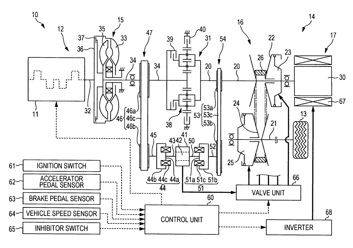
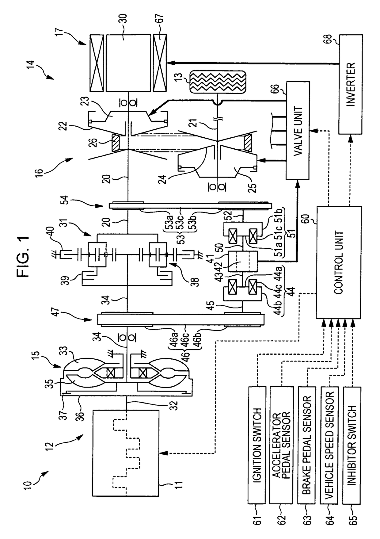
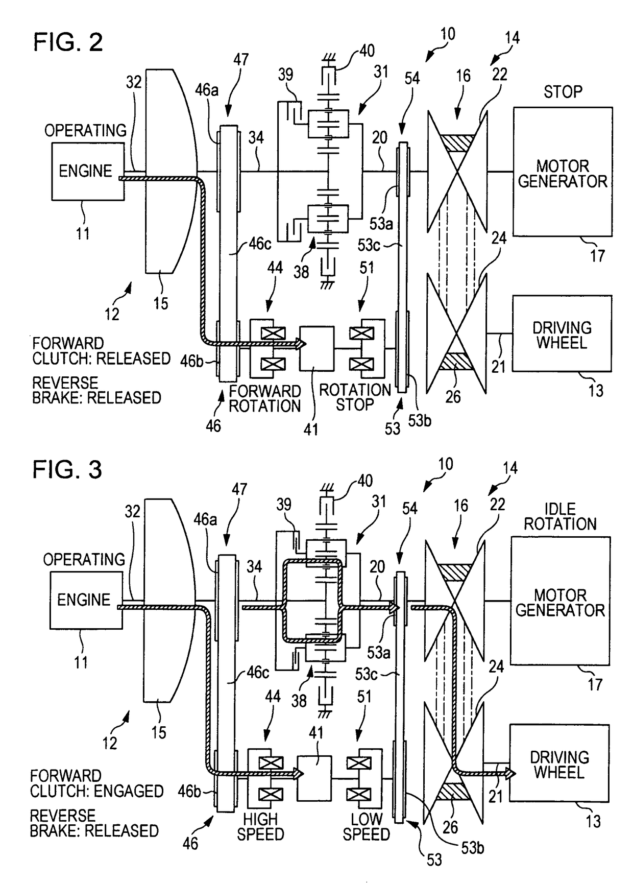
[0031]Embodiments according to the present invention will be described in detail below with reference to the drawings. FIG. 1 is an outline diagram illustrating a drive apparatus for a vehicle 10 according to an embodiment of the present invention. As illustrated in FIG. 1, the drive apparatus for a vehicle 10 includes an engine output system 12 and a power transmission system 14. The engine output system 12 outputs power from an engine 11, and the power transmission system 14 transmits the power from the engine Output system 12 to driving wheels 13. The engine output system 12 includes the engine 11 and a torque converter 15. The power transmission system 14 includes a continuously variable transmission (transmission mechanism) 16 and a motor generator 17. The power output from the engine 11 and the motor generator 17 is transmitted to each driving wheel 13 after the speed thereof is changed by a continuously variable transmission 16.

[0032]The continuously variable transmission 16 ...


PUM


Abstract

A drive apparatus for a vehicle includes an engine output system that outputs power from an engine and a power transmission system that transmits the power from the engine output system to a driving wheel. A power transmission path including a chain mechanism and a one-way clutch is provided between an oil pump and a turbine shaft that is part of the engine output system. Another power transmission path including a corresponding chain mechanism and a corresponding one-way clutch is provided between the oil pump and a primary shaft that is part of the power transmission system.

Description

CROSS-REFERENCE TO RELATED APPLICATIONS[0001]The present application claims priority from Japanese Patent Application No. 2010-219240 filed on Sep. 29, 2010, the entire contents of which are hereby incorporated by reference.BACKGROUND OF THE INVENTION[0002]1. Field of the Invention[0003]The present invention relates to a drive apparatus for a vehicle including an engine output system that outputs power from an engine and a power transmission system that transmits the power from the engine output system to a driving wheel.[0004]2. Description of the Related Art[0005]Driving methods of a hybrid vehicle that uses an engine and an electrical motor as drive sources includes a series method and a parallel method. In the series method, the engines is driven as a drive source for generating electrical power, and the electrical motor is driven as a drive source for running the vehicle. In the parallel method, the engine is driven as main drive source for running the vehicle, and the electric...

Claims


Application Information

Patent Timeline
Patent Type & Authority Patents(United States)
IPC IPC(8): F16H61/40F16H61/00B60K6/543B60K6/48B60L50/16
CPCB60K6/48B60K6/543F16H61/0028Y02T10/6221Y02T10/62
Inventor HIROSE, TAKASHISATO, KEIJIMARUYAMA, KEIICHIOKI, SHOGOINOUE, SATOSHI
Owner SUBARU CORP
Why Eureka
Try Eureka