Technique for using variable soil bearing capacity in foundation design

a technology of soil bearing capacity and foundation design, applied in the field of computer-aided foundation design, can solve the problems of large material cost, large amount of material cost, and large amount of material cost, and achieve the effect of small size and greater assurance of safety

Active Publication Date: 2017-06-13
BENTLEY SYST INC
View PDF1 Cites 10 Cited by
  • Summary
  • Abstract
  • Description
  • Claims
  • Application Information

AI Technical Summary

Benefits of technology

[0007]As a result of using variable soil parameters, for example variable soil bearing capacity, the computer-aided foundation design technique may produce foundation designs that are often of smaller size, yet have a greater assurance of safety, than designs produced by techniques that employ traditional fixed initial soil parameters, for example, fixed soil bearing capacity.

Problems solved by technology

However, this soil bearing capacity is generally not updated (i.e. remains fixed) as the foundation design evolves, for instance as the footing size, shape and embedment depth are refined by the structural engineer.
Knowing that initial soil parameters in the initial soil report, such as soil bearing capacity, are typically treated as fixed values throughout the design process, geotechnical engineers often provide overly conservative values.
The use of these overly conservative values often results in structural engineers specifying overly large footings, which incur excessive material costs.
Further, despite providing overly conservative values, in some cases, the final footing configuration specified by a structural engineer who has relied on the initial soil parameters in the initial soil report may still be unsafe.
While the values may be overly conservative within a certain range, if the foundation design evolved considerably, they could be inappropriate for the final footing configuration specified, leading to a false sense of security.

Method used


Image

  • Technique for using variable soil bearing capacity in foundation design
  • Technique for using variable soil bearing capacity in foundation design
  • Technique for using variable soil bearing capacity in foundation design

Examples


Embodiment Construction

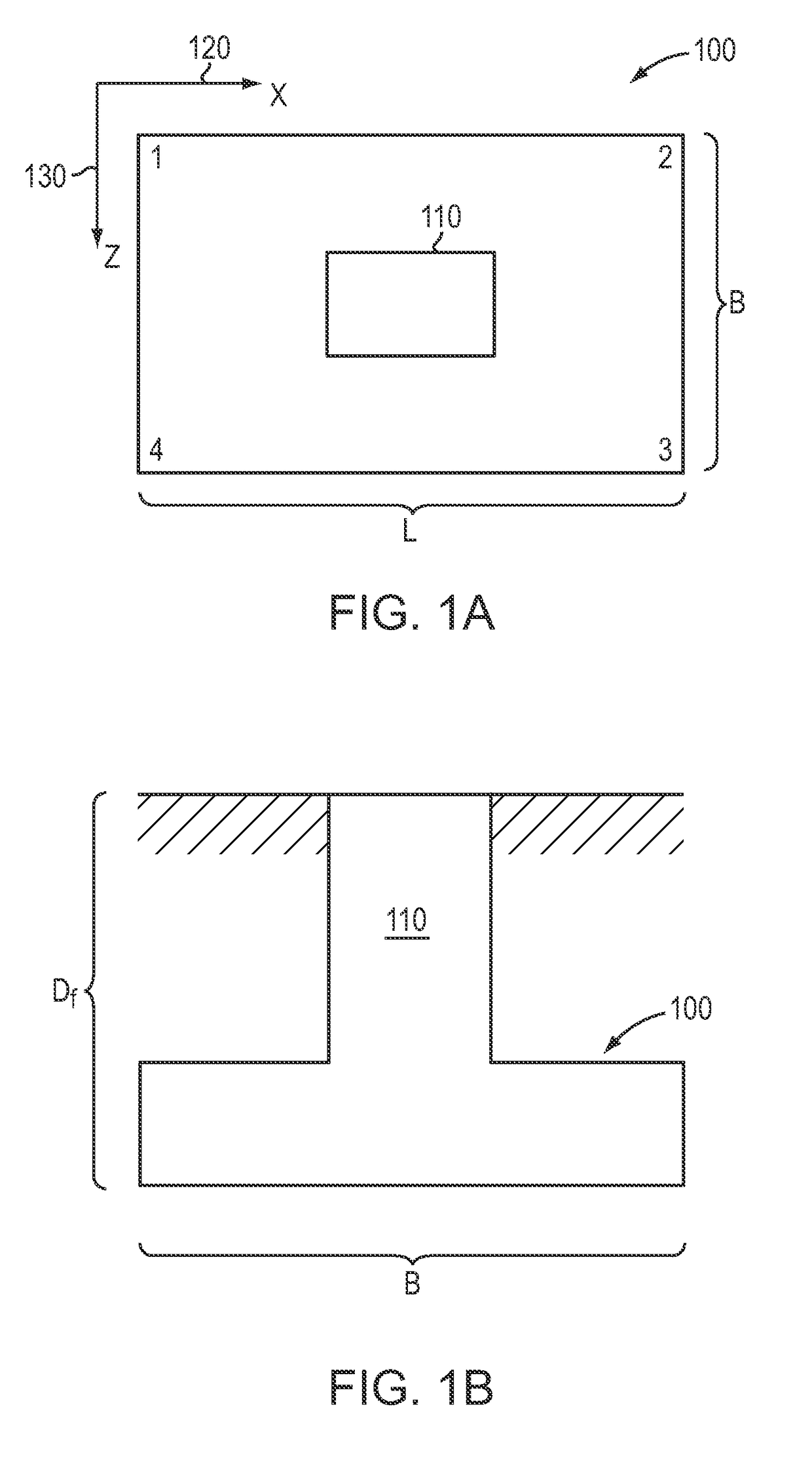
[0018]The issues presented in typical foundation design may be illustrated by reference to specific examples. Much of the discussion below refers to an example of a structural engineer tasked with designing a foundation that includes a rectangular (either square or strip) isolated footing. While such example may help illustrate the computer-aided foundation design technique described herein, it should be understood that the technique is applicable to a wide variety of foundation designs that include other types of foundations structures, for instance, wall footings, combined footings, cantilever or strap footings, or other types of structures.

[0019]FIG. 1A is a top-down view of an example isolated footing 100 designed to support a single column 110. The example isolated footing 100 is defined by a footing length (L) and footing width (B), referred to collectively (along with potentially a footing height) as “footing dimensions”. The example footing has four corners, which are refere...


PUM


Abstract

In one embodiment, a computer-aided foundation design technique employs variable soil parameters that are dynamically updated based on changes in footing shape, size, and/or embedment depth. The variable soil parameters may include a variable soil bearing capacity. The variable soil bearing capacity may be represented as a series of bearing capacity interaction curves that indicate an allowable bearing capacity for different footing dimensions and embedment depths. As part of the computer-aided foundation design technique, different combinations of footing dimensions and/or embedment depths may be iterated through, and for each iteration, base pressures may be tested against a soil bearing capacity that is specific to that combination of footing dimension and embedment depth.

Description

BACKGROUND[0001]Technical Field[0002]The present disclosure relates generally to computer-aided engineering design, and more specifically to computer-aided foundation design.[0003]Background Information[0004]Typically, foundation design is performed as a discrete process, with a geotechnical engineer providing a few initial soil parameters in an initial soil report, which are then used by a structural engineer to design the foundation. The initial soil parameters in the initial soil report provided by the geotechnical engineer are generally not updated (i.e. remain fixed) as the foundation design evolves. For example, the initial soil report may include a soil bearing capacity that is used in the design a footing of the foundation. However, this soil bearing capacity is generally not updated (i.e. remains fixed) as the foundation design evolves, for instance as the footing size, shape and embedment depth are refined by the structural engineer. Knowing that initial soil parameters in...

Claims


Application Information

Patent Timeline
Patent Type & Authority Patents(United States)
IPC IPC(8): G06F17/50
CPCG06F17/5004G06F30/20G06F30/13
Inventor TRIBEDI, APURBA
Owner BENTLEY SYST INC
Why Eureka
Try Eureka