Bullet comparator

a technology of bullet comparator and ring contact fixture, which is applied in the field of bullet comparator, can solve the problems of inconvenient adjustment of the alignment of the bullet by the ring contact fixture, and inability to accurately adjust the alignment of the bullet in the fixtur

Active Publication Date: 2017-06-20
HOLLAND DARRELL
View PDF2 Cites 2 Cited by
  • Summary
  • Abstract
  • Description
  • Claims
  • Application Information

AI Technical Summary

Benefits of technology

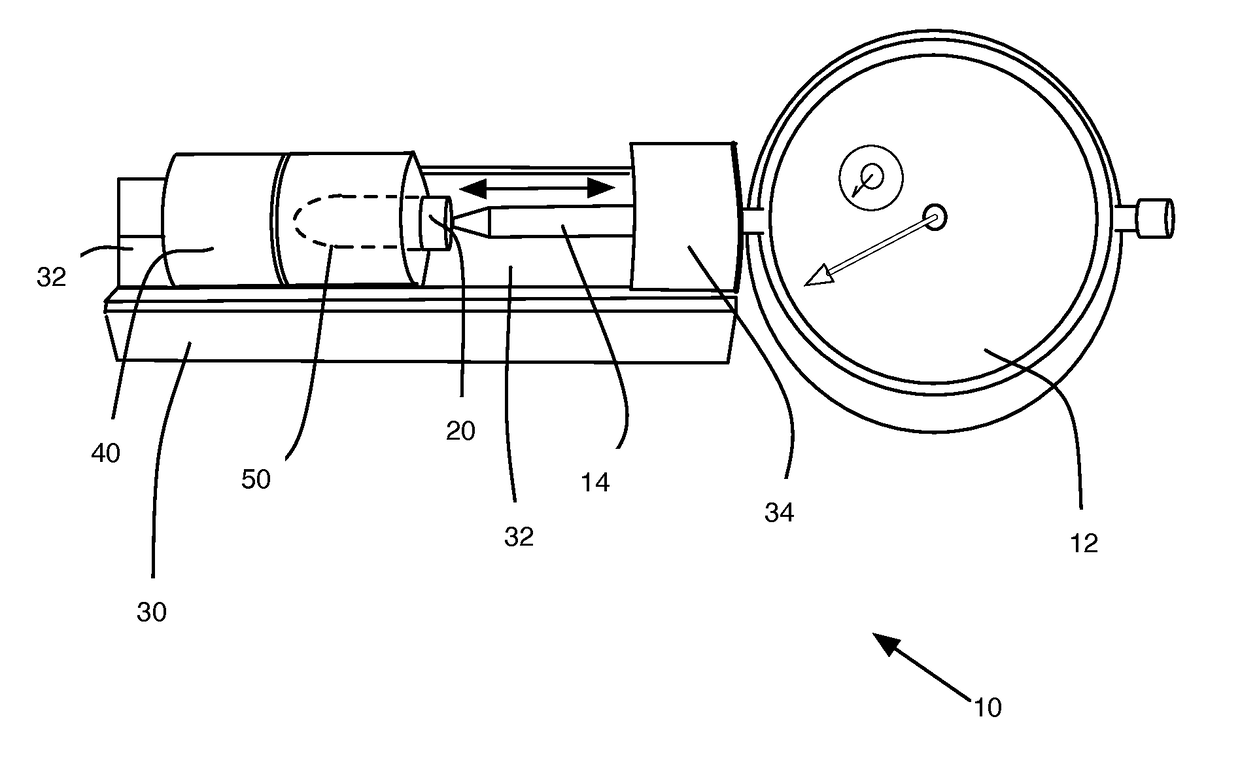
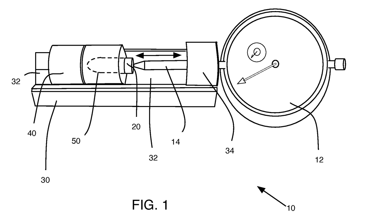
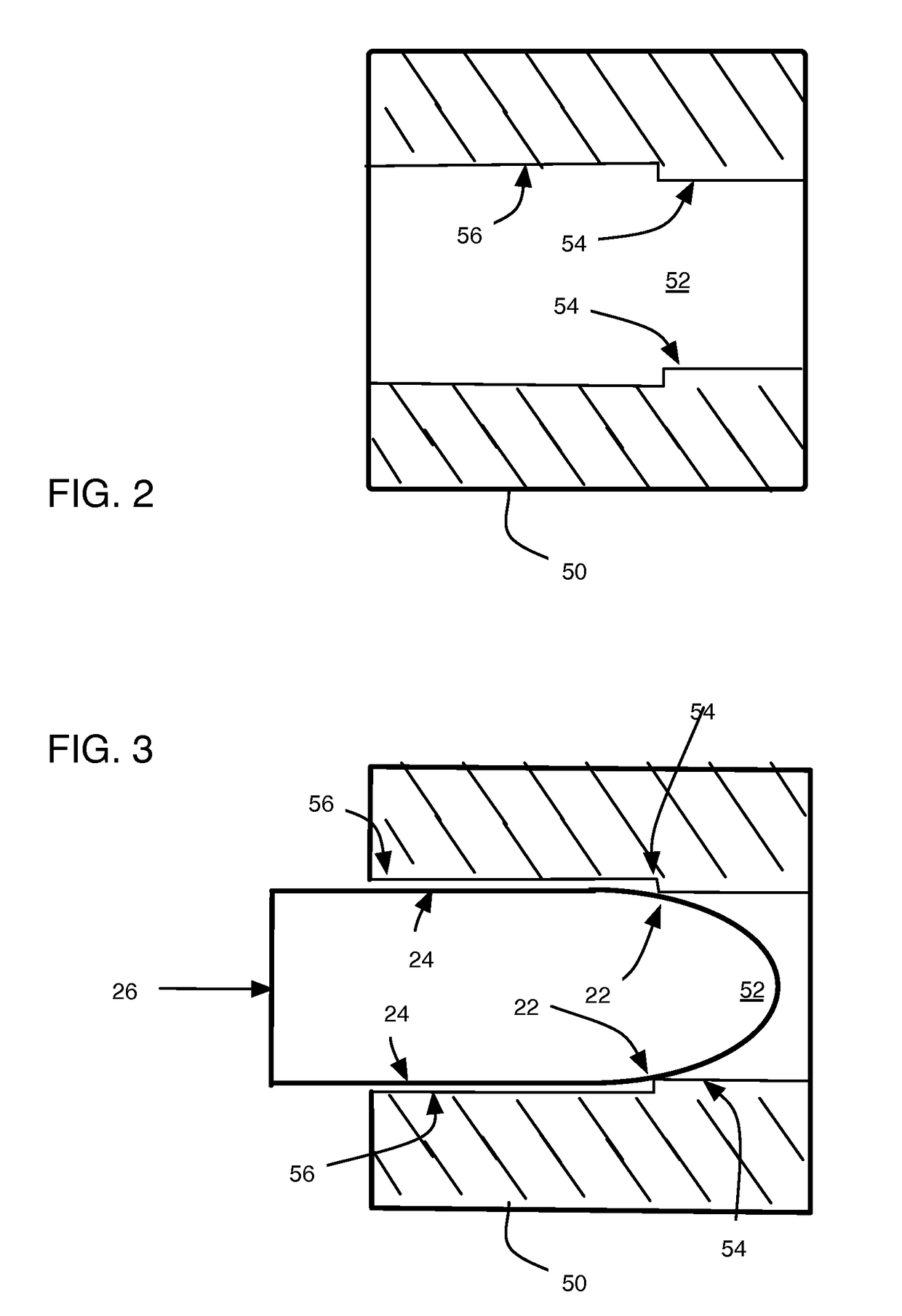
[0008]The unique floating bullet chamber of the present invention holds the bullet's base square to the bullet's central axis and datum line. The floating bullet chamber uses a multiple point contact geometry inside the fixture to provide a first ring-contact line about the bullet's circumference and at least one additional (second) ring-contact line. This ensures a repeatable and consistent placement of the bullet in the chamber each and every time a bullet is placed in the floating bullet chamber.
[0009]Spring tension caused by the operation of the dial indicator against the bullet, which is supplied by the internal spring of the dial indicator, provides a consistent and uniform compression of the bullet into the floating chamber. This ensures repeatability to plus or minus 0.0002-0.0003 of an inch.
[0013]The speed and rapidity at which one can precisely sort bullets is un-equaled with this gauge. The stationary base and gauge design allows the user to use both hands to sort bullets. One gently inserts a bullet into the correct size floating chamber, retracting the dial stem and inserting the bullet tip into the relief hole in the adjustable stop block. The floating chamber is nestled in the V-shaped grove of the precision Fixture and the dial stem compresses the bullet against the datum contact point within the floating chamber. The reverse procedure is used to remove the bullet and floating chamber the bullet is ejected from the floating chamber with the middle finger to the specific container based on its dimension.

Problems solved by technology

However, this approach causes considerable variability because repeatable and proper alignment of the bullet by the ring-contact fixture is imprecise.
The bullet is placed in the ring-contact fixture; however, it is very easy to misalign the bullet in the fixture.
A common problem with this fixture is that a bullet can be off-center in the borehole, thus making repeatable measurements on the same bullet difficult.

Method used


Image

  • Bullet comparator
  • Bullet comparator
  • Bullet comparator

Examples


Embodiment Construction

[0023]Possible embodiments will now be described with reference to the drawings and those skilled in the art will understand that alternative configurations and combinations of components may be substituted without subtracting from the invention. Also, in some figures certain components are omitted to more clearly illustrate the invention.

[0024]The disclosure uses the term bullet, cartridge, and fire arm projectile interchangeably. This use should not be limiting and refers generally to a typically metal projectile in the shape of a pointed cylinder that is expelled from a firearm, especially a rifle or handgun. This projectile further typically includes a metal casing.

[0025]FIGS. 6 and 7 illustrate a representative bullet of a given gauge and these figures will aid in understanding some of the terminology used herein. A typical bullet 601 includes a nose 603 at a distal end and an opposite base 605 at a proximal end. A bullet body 607 links and is intermediate to both the nose and ...


PUM


Abstract

The present invention provides a device and method for improved, repeatable, consistent, rapid, and accurate measurements of a bullet using a dial indicator. The bullet comparator of the present invention consists of a fixture block having a V-shaped groove running along a long axis of the block and a dial indicator coupled to one end of the fixture, configured so its probe operably moves toward the center of the fixture. A stop block adjustably positions in the V-shaped grove of the fixture. And, at least one floating chamber selectively positions in the V-shaped grove of the fixture. The floating chamber is a cylindrical body defining an interior chamber; the interior chamber has a first ring-contact and at least a second ring-contact on an interior portion of the chamber.

Description

PRIORITY CLAIM[0001]The present application is based on, and claims priority to for all purposes, provisional patent application No. 61 / 942,235, filed on 20 Feb. 2014 having the common inventor named above.FIELD OF THE INVENTION[0002]The present invention relates to systems, methods, and devices used to precisely, accurately, and repeatedly determine the overall length of a small-arms ballistics (bullets).BACKGROUND[0003]The current teaching in the art relies heavily on user skill and dexterity to determine the size (overall length) of a bullet. Common bullet comparators rely upon the user's ability to juggle the bullet into place to hopefully find a datum line from which to measure. This datum line, however, is a constructed line that relies on a visual queue based on a single ring-contact line, or datum-line, established by a fixture holding the bullet around its circumference and a single touch-point on the bullet's base, where the measuring instrument contact's the bullet. Howev...

Claims


Application Information

Patent Timeline
Patent Type & Authority Patents(United States)
IPC IPC(8): F42B35/02
CPCF42B35/02
Inventor HOLLAND, DARRELL
Owner HOLLAND DARRELL
Why Eureka
Try Eureka