Device for measuring the faces of a crank bearing

a technology for crank bearings and measuring devices, which is applied in the direction of measuring devices, mechanical roughness/irregularity measurements, instruments, etc., can solve the problem of time-consuming chucking operation, and achieve the effect of reducing the required time expenditur

Inactive Publication Date: 2017-06-20
JENOPTIK IND METROLOGY GERMANY
View PDF20 Cites 9 Cited by
  • Summary
  • Abstract
  • Description
  • Claims
  • Application Information

AI Technical Summary

Benefits of technology

[0012]An object of the invention is to provide a crank bearing face measuring device for measuring the faces of crank bearings of a crankshaft, which reduces the required time expenditure during the measurement of crank bearings of a crankshaft.
[0017]Since according to the invention, the measuring head follows orbital rotations of the crank pin, the crank bearing faces may be measured while the crankshaft is rotated about the main axis of rotation defined by the main bearings of the crankshaft. A measurement of the main bearings and of the crank bearings may thus take place in the same chucking position of the crankshaft, so that rechucking is dispensed with. Measuring the faces of bearings of a crankshaft is thus particularly time-saving. This lowers costs, in particular for mass production.
[0018]When using the device according to the invention, when at least two measuring heads are used, it is also possible in particular to simultaneously measure at least one main bearing and at least one crank bearing of the crankshaft, which saves even more time in the measuring operation. In principle, it is also possible to measure all bearings of the crankshaft at the same time when the number of measuring heads provided corresponds to the number of bearings.
[0021]In the above-mentioned embodiment, the rod assembly may be configured in any desired way that meets the particular requirements. In this regard, one advantageous further embodiment provides that the rod assembly has a first rod assembly element which on the one hand is connected to the base body about rotational axes that are parallel to the main axis of rotation, and on the other hand is connected to one end of a second rod assembly element, whose other end is connected to the measuring head, or to a component that is connected thereto, about a rotational axis that is parallel to the main axis of rotation. This embodiment provides a rod assembly which has a simple, and therefore economical and robust, configuration with a minimal number of components, and which achieves a connection of the measuring head to the base body in which the measuring head is able to follow orbital rotations of the crank pin during rotation of the crankshaft about the main axis of rotation. In this regard, a minimal number of rod assembly elements is also advantageous due to the fact that the number of articulated joints on the one hand between the rod assembly elements, and on the other hand among the rod assembly elements and between the measuring head and the base body, is minimized, so that effects on the measuring results due to play or manufacturing tolerances in or on the articulated joints are minimized.
[0023]According to the invention, it is sufficient in principle for the measuring head to have a single measuring probe. One extremely advantageous further embodiment of the invention provides that the measuring head has two measuring probes which scan in opposite scanning directions in order to simultaneously contact oppositely situated faces of a crank bearing. In this embodiment, the two oppositely situated faces of a crank bearing are simultaneously contacted and measured by means of the two measuring probes, thus further reducing the time expenditure for measuring the crank bearings of a crankshaft.

Problems solved by technology

In this regard, it is disadvantageous that the rechucking operation is time-consuming.

Method used


Image

  • Device for measuring the faces of a crank bearing
  • Device for measuring the faces of a crank bearing
  • Device for measuring the faces of a crank bearing

Examples


Embodiment Construction

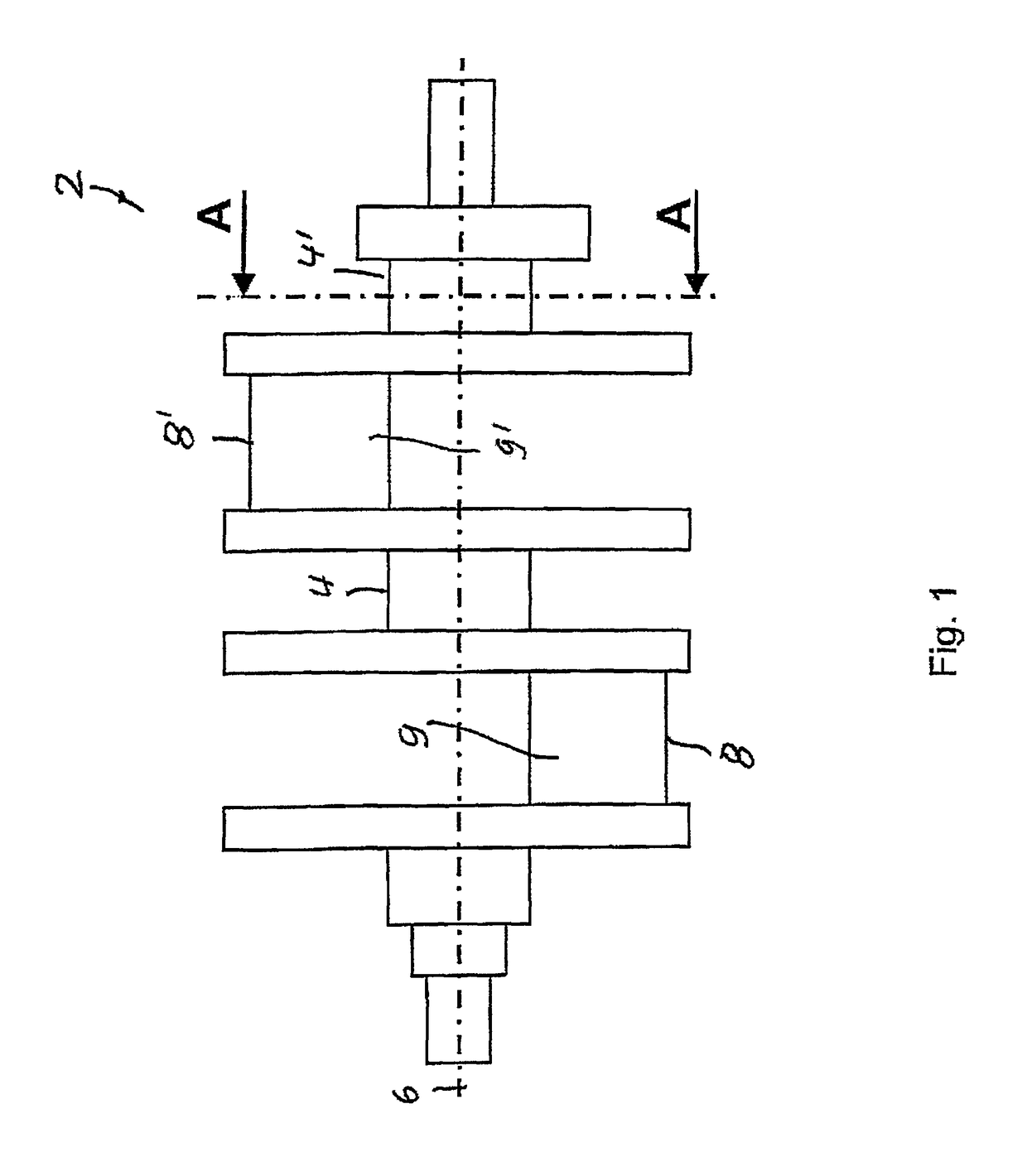
[0037]FIG. 1 illustrates a crankshaft 2 having main bearings 4, 4′ which define a main axis of rotation 6. The crankshaft 2 also has crank bearings 8, 8′ which are situated eccentrically with respect to the main axis of rotation 6, and which thus undergo an orbital rotation when the crankshaft 2 rotates about the main axis of rotation 6. The crank bearings 8, 8′ are formed on cylindrical crank pins 9, 9′. In other respects, the basic design of a crankshaft is generally known to those skilled in the art, and therefore is not explained here in greater detail.

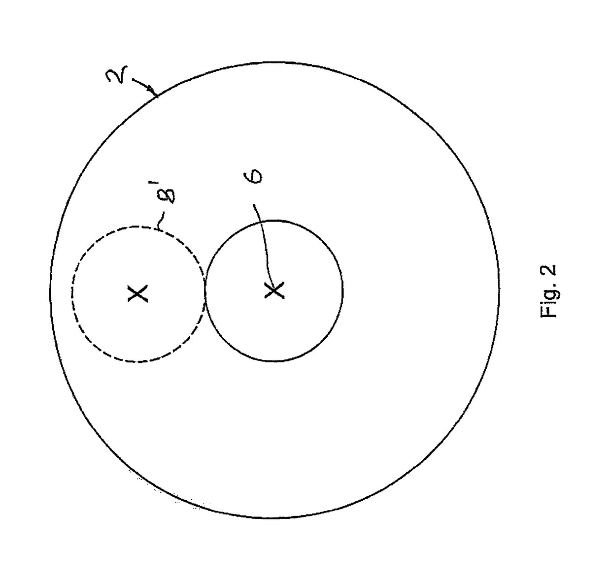
[0038]It is apparent from FIG. 2, which shows a section along a line A-A in FIG. 1, that the crank bearing 8′ is situated eccentrically with respect to the main bearing 4 and the main axis of rotation 6. The same applies for the crank bearing 8.

[0039]FIG. 3 shows, in enlarged scale, a detail from FIG. 1 in the area of the crank bearing 8, illustrating the geometry of the crank bearing 8 in greater detail. The crank bearing 8 has o...


PUM


Abstract

A crank bearing face measuring device for measuring the faces of crank bearings of a crankshaft has a base body and a device for rotating the crankshaft about a main axis of rotation. The main axis of rotation is defined by the main bearings of the crankshaft. Measuring device also has a measuring head which has a probe prism for placing against a crank pin of the crankshaft, and at least one measuring probe, for placing against a face of the crank bearing to be measured. The measuring head is configured for and connected to the base body in such a way that the measuring head follows an orbital rotation of the crank pin during rotation of the crankshaft about the main axis of rotation.

Description

CROSS-REFERENCE TO RELATED APPLICATIONS[0001]This application claims the priority of German Application No. DE 10 2014 113 553, filed 19, Sep. 2014, which is incorporated herein by reference.FIELD OF THE INVENTION[0002]The invention relates to a crank bearing face measuring device for measuring the faces of crank bearings of a crankshaft.BACKGROUND OF THE INVENTION[0003]In the manufacture of crankshafts it is necessary to measure main bearings of the crankshaft, which define a main axis of rotation of the crankshaft, as well as crank bearings on crank pins which are situated eccentrically with respect to the main axis of rotation. The measurement is used, for example and in particular, to check the axial runout properties of the faces of the main bearings and of the crank bearings.[0004]For carrying out the necessary measurements, the crankshaft is initially clamped in such a way that it is rotated about its main axis of rotation, and during the rotation of the crankshaft the faces ...

Claims


Application Information

Patent Timeline
Patent Type & Authority Patents(United States)
IPC IPC(8): G01B7/00G01B5/28G01M13/04G01B5/00
CPCG01M13/04G01B5/003G01B5/285
Inventor DIETZ, GUIDOHAUPTMANNL, MICHAEL
Owner JENOPTIK IND METROLOGY GERMANY
Why Eureka
Try Eureka