System and method for equipment monitoring component configuration

a technology for monitoring components and configuration information, applied in the field of equipment monitoring components configuration, can solve the problems of inaccurate or incomplete configuration information that directs the operation of the monitoring apparatus for communicating with the equipment monitoring components, time-consuming and laborious typical procedure for configuring such a communication interface, etc., to achieve the effect of reducing time expenditure and improving accuracy

Active Publication Date: 2013-03-28
BAKER HUGHES INC
View PDF1 Cites 4 Cited by
  • Summary
  • Abstract
  • Description
  • Claims
  • Application Information

AI Technical Summary

Benefits of technology

[0007]An advantage that may be realized in the practice of some disclosed embodiments is reduced expenditure of time and improved accuracy when configuring a communications interface between a monitoring apparatus and one or more equipment monitoring components.

Problems solved by technology

The typical procedure for configuring such a communications interface can be time consuming and vulnerable to inaccuracy.
Any information that may be required to be entered into the user interface of the monitoring apparatus may have been recorded inaccurately or not at all by the user.
As a result, the configuration information that directs the operation of the monitoring apparatus for communicating with the equipment monitoring components may be inaccurate and / or incomplete.
The user may or may not recognize that the entered configuration information is inaccurate or incomplete.
If such a configuration problem is not recognized by the user, the user will cease attempting to properly configure the monitoring apparatus and as a result, the monitoring apparatus will be permitted to operate while being directed by incomplete and / or inaccurate configuration information, potentially causing incorrect processing of signals received from the equipment monitoring components.

Method used


Image

  • System and method for equipment monitoring component configuration
  • System and method for equipment monitoring component configuration
  • System and method for equipment monitoring component configuration

Examples


Embodiment Construction

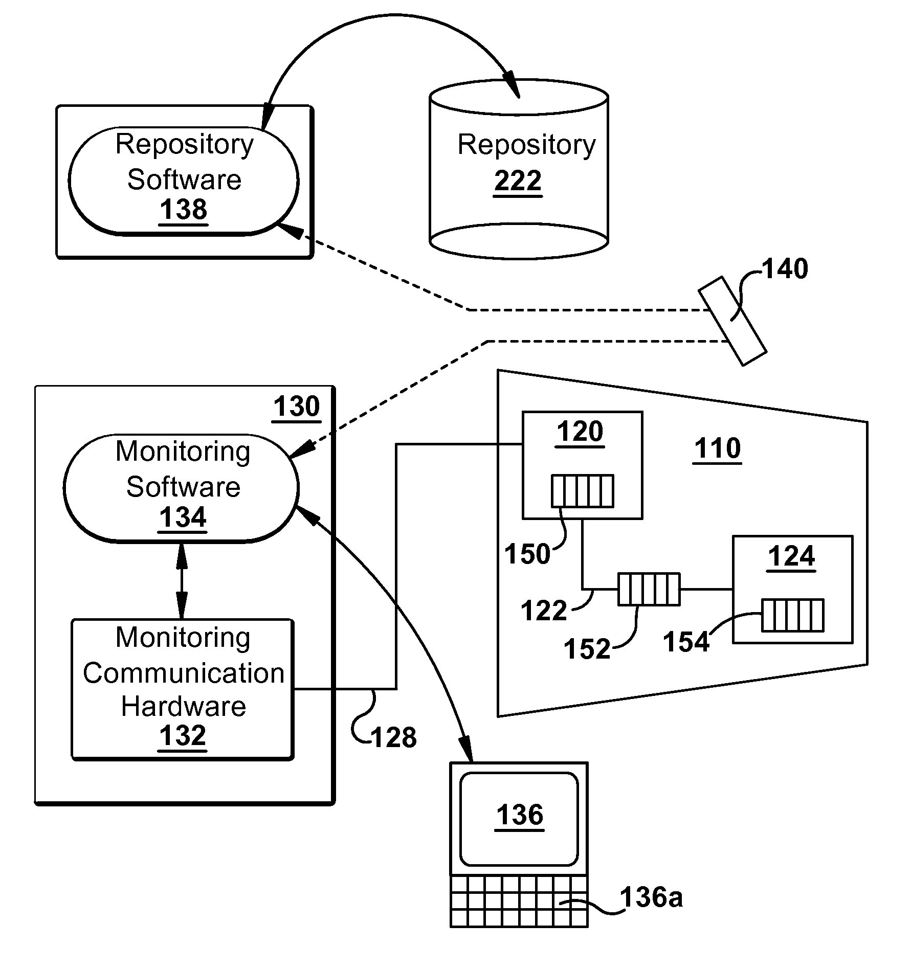
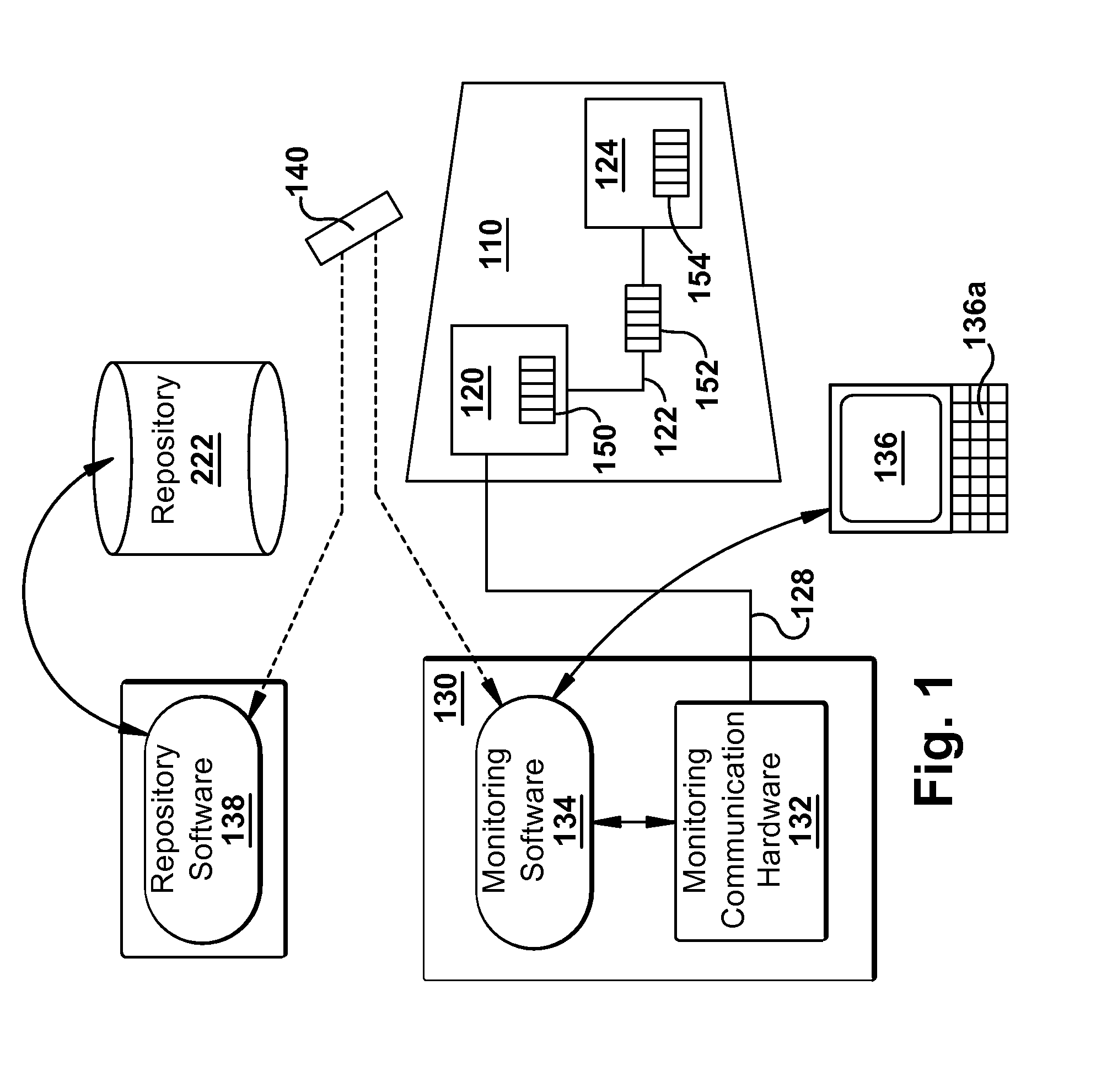
[0017]FIG. 1 is a diagram illustrating an exemplary embodiment of a system 100 for monitoring the operation of industrial plant equipment, such as a turbine 110. As shown, a set of equipment monitoring components 120-124, typically including sensors, electronics and transducers, are designed for interfacing with each other for the purpose of monitoring the operation of selected equipment, such as the turbine 110, and are shown disposed along an outer surface of a turbine 110. Generally, such components are disposed proximate to, adjacent or inside of a particular unit of industrial plant equipment. In this exemplary embodiment, a cable 128 provides an electrical connection, between at least one of the equipment monitoring components 120-124 and a monitoring apparatus 130.

[0018]As shown, machine readable codes 150-154 are each respectively attached to each respective component 120-124. Machine readable code 150 is attached to component 120, machine readable code 152 is attached to co...


PUM


Abstract

A system and method for configuring a communications interface between a monitoring apparatus and one or more equipment monitoring components is disclosed. The equipment monitoring components are designed to physically and / or electrically interface with each other while in proximity to equipment being monitored. Each of these components has a proximately disposed unique associated machine readable code. A set of configuration information is also associated with the machine readable code. The codes are scanned and mapped to the configuration information in order to automate configuration of communication between the monitoring apparatus and equipment monitoring components.

Description

BACKGROUND OF THE INVENTION[0001]The subject matter disclosed herein relates to configuring equipment monitoring components.[0002]Industrial plants are designed to employ various types of components for monitoring the operation of other equipment within the plant. These components may be physically and / or electrically attached with each other and may have a communication interface with a remotely located monitoring apparatus. Such a communication interface is typically required to be configured for proper and accurate operation of the monitoring apparatus. The typical procedure for configuring such a communications interface can be time consuming and vulnerable to inaccuracy.[0003]In a typical system, a user walks to within viewing proximity of the equipment (e.g., a turbine) and then identifies characteristics and external markings that are visible on each monitoring component, such as the type, manufacture and model of each component, and then records such information, such as for...

Claims


Application Information

Patent Timeline
Patent Type & Authority Applications(United States)
IPC IPC(8): G06F17/00
CPCG05B23/0216
Inventor CAMPBELL, LAM ARTHURCLARK, SHERRIE ANNJENSEN, RAYMOND VERLEHATCH, CHARLES TERRANCE
Owner BAKER HUGHES INC
Why Eureka
Try Eureka