Method for examining a test sample using a scanning probe microscope, measurement system and a measuring probe system

a scanning probe and microscope technology, applied in the direction of measuring devices, nanotechnology, instruments, etc., can solve the problems of cell death, no physiological conditions, and ageing that cannot only occur, and achieve the effect of reducing time expenditur

Active Publication Date: 2013-02-19
JPK INSTR +1
View PDF15 Cites 5 Cited by
  • Summary
  • Abstract
  • Description
  • Claims
  • Application Information

AI Technical Summary

Benefits of technology

[0014]The object of the invention is to provide an improved method for examining a test sample using a scanning probe microscope, in particular for examining a test sample using a scanning probe microscope, a measurement system and a measuring probe system which allow for the implementation of examinations using a scanning probe microscope in a simplified manner and with reduced time expenditure, where in particular the elaborate replacement of the measuring probe should be required less often.
[0017]During the second measurement, in relation to the test sample, the measuring probe is then held in the non-measurement position and the other measuring probe is held in the other measurement position, and the test sample is examined with the other measuring probe using a scanning probe microscope. In this way, the implementation of the measurement using a scanning probe microscope which comprises a first measurement stage and a second measurement stage is made possible without it being required that a replacement of the measuring probe takes place. In fact, the measuring probe and the other measuring probe which are both arranged on the common measuring probe receptacle are brought into the allocated measurement position or the allocated non-measurement position, depending on the current measurement stage. In this way, examinations using a scanning probe microscope, in particular by means of a scanning probe microscope, can be carried out with reduced time expenditure and more convenient for the user.
[0019]An allocated measurement position of a measuring probe is characterized in that an interaction between measuring probe and test sample to be examined which serves the examination using a scanning probe microscope can take place in this position. In contrast, in the case of an allocated non-measurement position, an interaction between measuring probe and sample to be examined which serves the measurement using a scanning probe microscope does not take place. The latter can be achieved, for example, by choosing the distance between measuring probe, in particular an measuring-active measuring probe part, and the test sample to be examined that high that a metrological relevant interaction does not take place. However, a non-measurement position can also be created when the measuring-active measuring probe part is pressed onto the test sample, namely in such a manner that any metrological contribution to the examination using a scanning probe microscope is prevented and suppressed. For example, after it was used for a previously performed measurement, the measuring-active measuring probe part can simply be moved along on a surface section of the test sample, scratching said section.
[0032]In an advantageous implementation of the invention, it can be provided for the measuring probe during the displacement from the measurement position into the non-measurement position being arranged above an area of the test sample which was already previously examined using a scanning probe microscope. This results in the advantage that the measuring probe cannot damage any sections of the test sample still to be examined in the non-measurement position as, in the non-measurement position, it is positioned in areas of the test sample which were already examined. Such an implementation of the method can be obtained, for example, by gradually examining the test sample along an examination path with several measuring probes using a scanning probe microscope, the sections along the examination path being examined consecutively in a maintained advance direction. This type of examination also makes it possible, for example, to simply bring a measuring probe after its use for the examination using a scanning probe microscopy into a non-measurement position in which the measuring probe scratches along the surface of the test sample, this surface contact only occurring in areas which were already examined.

Problems solved by technology

If a pre-treated cantilever is used in the distance spectroscopy, several handling problems result in practice.
The probe substance applied to the measuring probe is usually burdened by each mechanical contact with the sample in such a way that ageing of the probe substance occurs after one or more individual experiments.
However, ageing can not only occur due to the implementation of measurements, but also without such a measurement, for example, when using a probe substance in the form of a cell, no physiological conditions set for the cell are given before or also during the measurement.
The implementation of the probe substance as a cell coating in which often only one cell fits onto the cantilever can result in the cell dying and changing very significantly already before performing the measurement experiment, thus it not being possible any longer to perform the actual measurement.
This can also lead to incorrect measurement results if this event is taking place unnoticed.
Using an untreated cantilever can lead to an adsorbate being formed through the contact with the sample such that even unspecific bonds are no longer possible.
Besides the measurements mentioned above, other measurements are also affected by the damaging, for example imaging methods, in particular by the damaging of the probe tip relevant to the interactions.
However, as the tip is damaged by the scratching process, it is no longer possible to obtain an image of good quality.
If an ageing process interfering with or even preventing the measurement or else another undesired damaging of the measuring probe has occurred, this being pre-treated or untreated, the measuring probe is usually replaced.
This replacement of the measuring probe takes time as it normally can only be performed manually.
Another disadvantage of the replacement of the probe is that a contamination of the measurement environment, for example the fluid or also the sample itself, becomes more likely with each replacement process.
Furthermore, a disadvantage is that after the replacement of the base, it is no longer possible to find a sample point again at once.
However, this procedure involves considerable expenditure both in terms of the production of the measuring probe and the equipment.

Method used


Image

  • Method for examining a test sample using a scanning probe microscope, measurement system and a measuring probe system
  • Method for examining a test sample using a scanning probe microscope, measurement system and a measuring probe system
  • Method for examining a test sample using a scanning probe microscope, measurement system and a measuring probe system

Examples


Embodiment Construction

[0042]In the following, the invention is explained in more detail using exemplary embodiments with reference to figures of a drawing. They show:

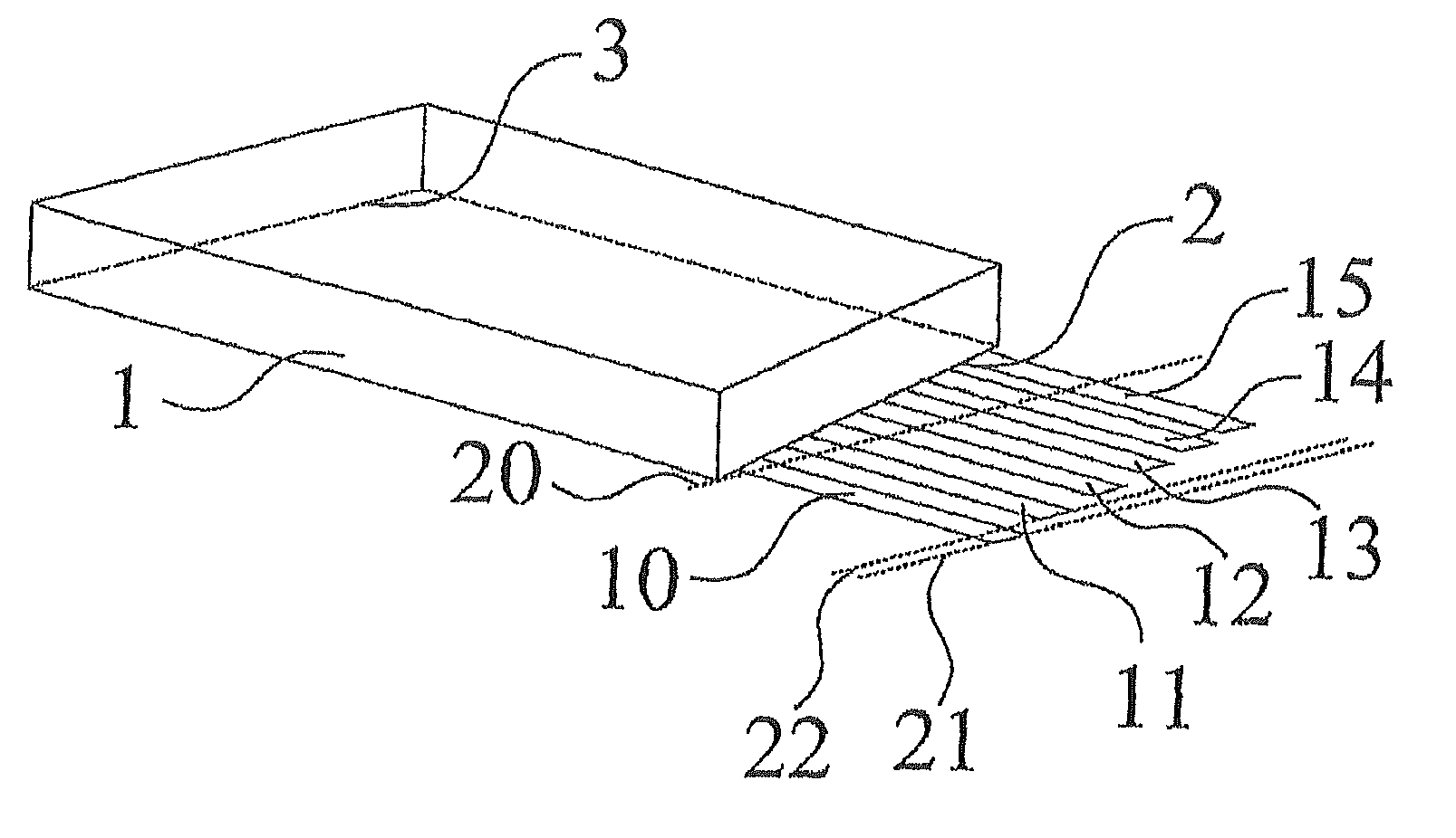
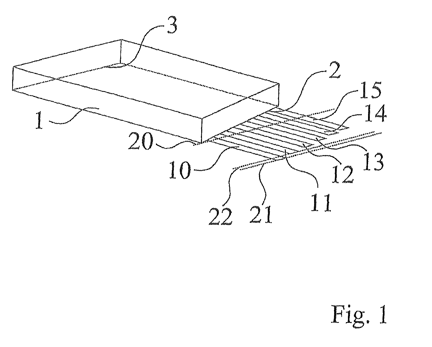
[0043]FIG. 1 an arrangement with a measuring probe receptacle, several measuring probes being jointly formed thereon;

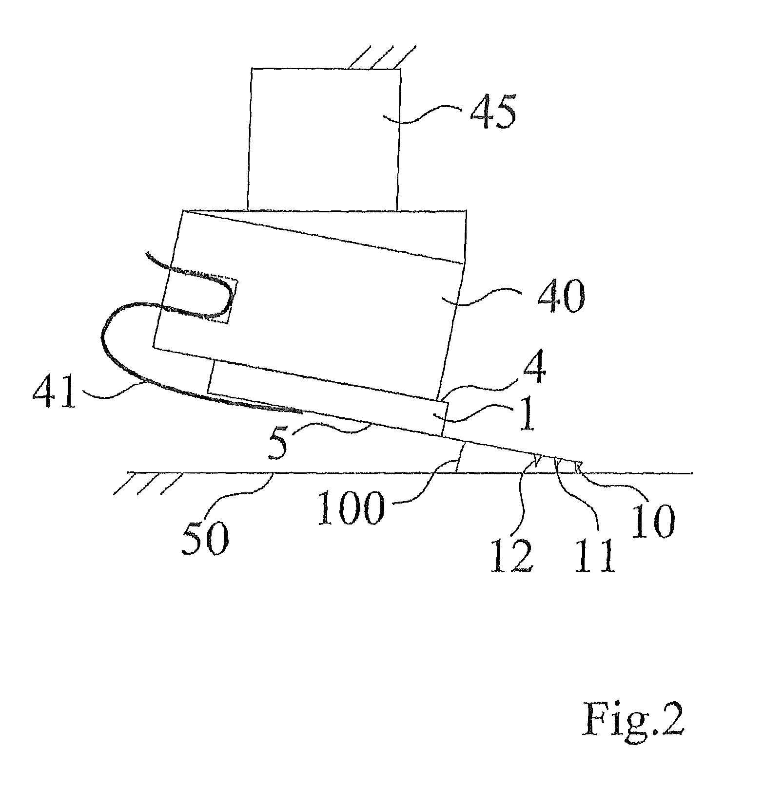
[0044]FIG. 2 an arrangement with a measuring probe receptacle, several measuring probes being jointly arranged thereon, and a measuring probe displacement means to which the common measuring probe receptacle is coupled;

[0045]FIG. 3 several depictions to illustrate the displacement of measuring probes being jointly formed on the measuring probe receptacle between measurement position and non-measurement position;

[0046]FIG. 4 a flowchart; and

[0047]FIG. 5 another arrangement with a measuring probe receptacle and several measuring probes formed thereon.

[0048]FIG. 1 shows an arrangement with a measuring probe receptacle 1, also being shortened referred to as a base, several measuring probes or probes 10, . . . , 15 being arranged t...


PUM


Abstract

The invention relates to a method and to a device for examining a test sample using a scanning probe microscope. According to the method a first and a second measurement using a scanning probe microscope are carried out on the test sample using a measuring probe system in which a measuring probe and another measuring probe are formed on a common measuring probe receptacle. During the first measurement, in relation to the test sample, the measuring probe is held in a first measurement position and the other measuring probe is held in another non-measurement position, and the test sample is examined with the measuring probe using a scanning probe microscope. After the first measurement, by displacing in relation to the test sample, the measuring probe is displaced from the measurement position into a non-measurement position and the other measuring probe from the other non-measurement position into another measurement position. During the second measurement, in relation to the test sample, the measuring probe is held in the non-measurement position and the other measuring probe is held in the other measurement position, and the test sample is examined with the other measuring probe using a scanning probe microscope. The invention also relates to a measuring sensor system of a scanning probe microscope.

Description

[0001]The invention relates to a method for examining a test sample using a scanning probe microscope, in particular for examining using a scanning probe microscope, a measurement system and a measuring probe system.BACKGROUND OF THE INVENTION[0002]Scanning probe microscopy (SPM) is a measurement and analysis technique in which a measuring probe scans a sample of a measurement medium to be examined and a topography of the sample is determined via a distance-dependent interaction between the measuring probe and the sample. However, matter constants or other sample information can also be obtained. The most prominent examples of this technique are the atomic force microscope (AFM) and the scanning tunneling microscope (STM). Further examples of this technology are in particular the scanning near field microscope (SNOM) and the scanning photon microscope (SPhM). Furthermore, an examination method classified as scanning probe microscopy is the recording of a force-distance curve in whic...

Claims


Application Information

Patent Timeline
Patent Type & Authority Patents(United States)
IPC IPC(8): G01Q10/00
CPCG01Q70/06B82Y35/00
Inventor JAHNKE, TORSTEN
Owner JPK INSTR
Why Eureka
Try Eureka