Device for measuring the faces of a crank bearing
a technology for crank bearings and measuring devices, which is applied in the direction of measuring devices, machine bearing testing, instruments, etc., can solve the problems of time-consuming chucking operation, and achieve the effect of reducing the required time expenditur
- Summary
- Abstract
- Description
- Claims
- Application Information
AI Technical Summary
Benefits of technology
Problems solved by technology
Method used
Image
Examples
Embodiment Construction
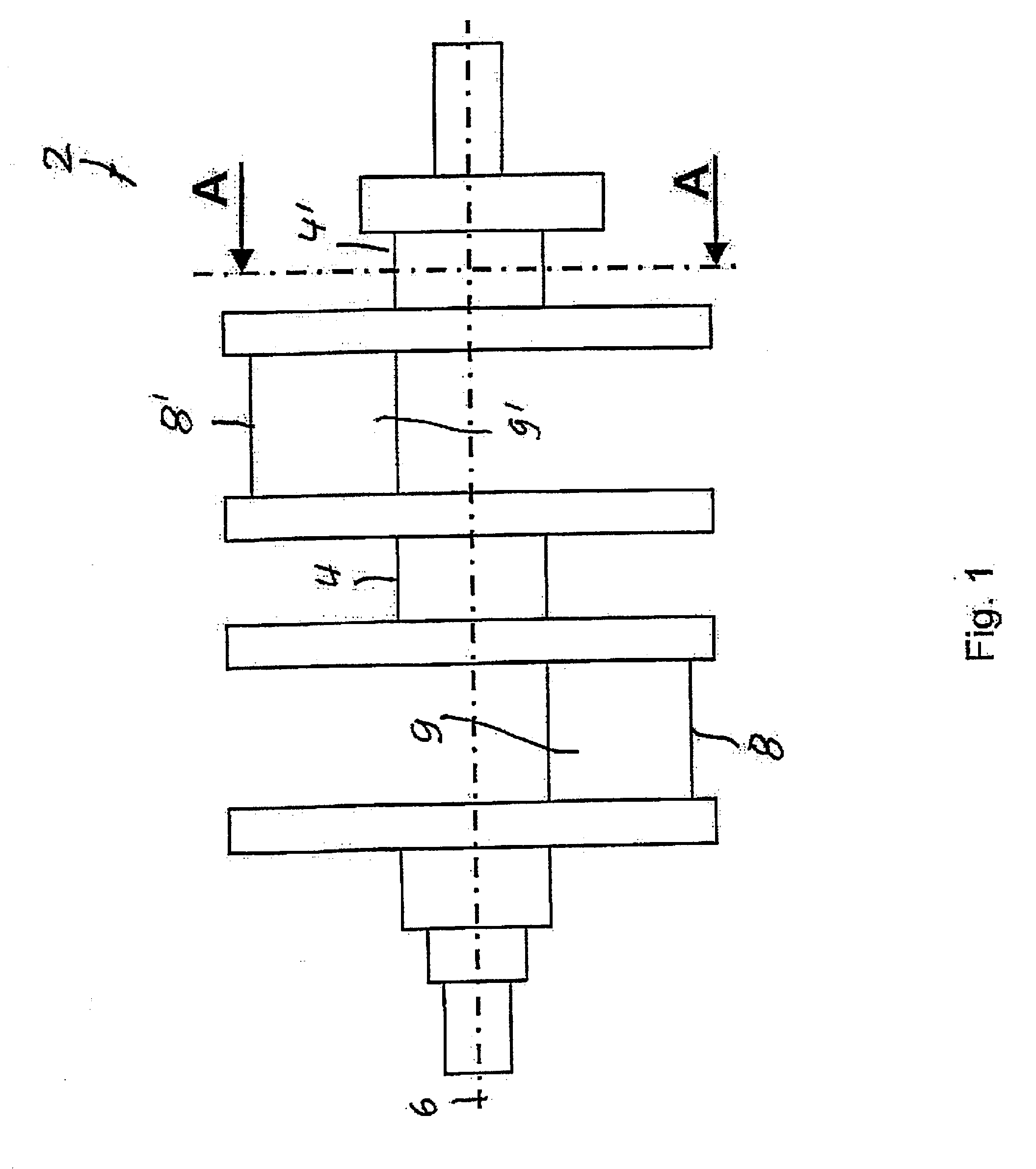
[0037]FIG. 1 illustrates a crankshaft 2 having main bearings 4, 4′ which define a main axis of rotation 6. The crankshaft 2 also has crank bearings 8, 8′ which are situated eccentrically with respect to the main axis of rotation 6, and which thus undergo an orbital rotation when the crankshaft 2 rotates about the main axis of rotation 6. The crank bearings 8, 8′ are formed on cylindrical crank pins 9, 9′. In other respects, the basic design of a crankshaft is generally known to those skilled in the art, and therefore is not explained here in greater detail.
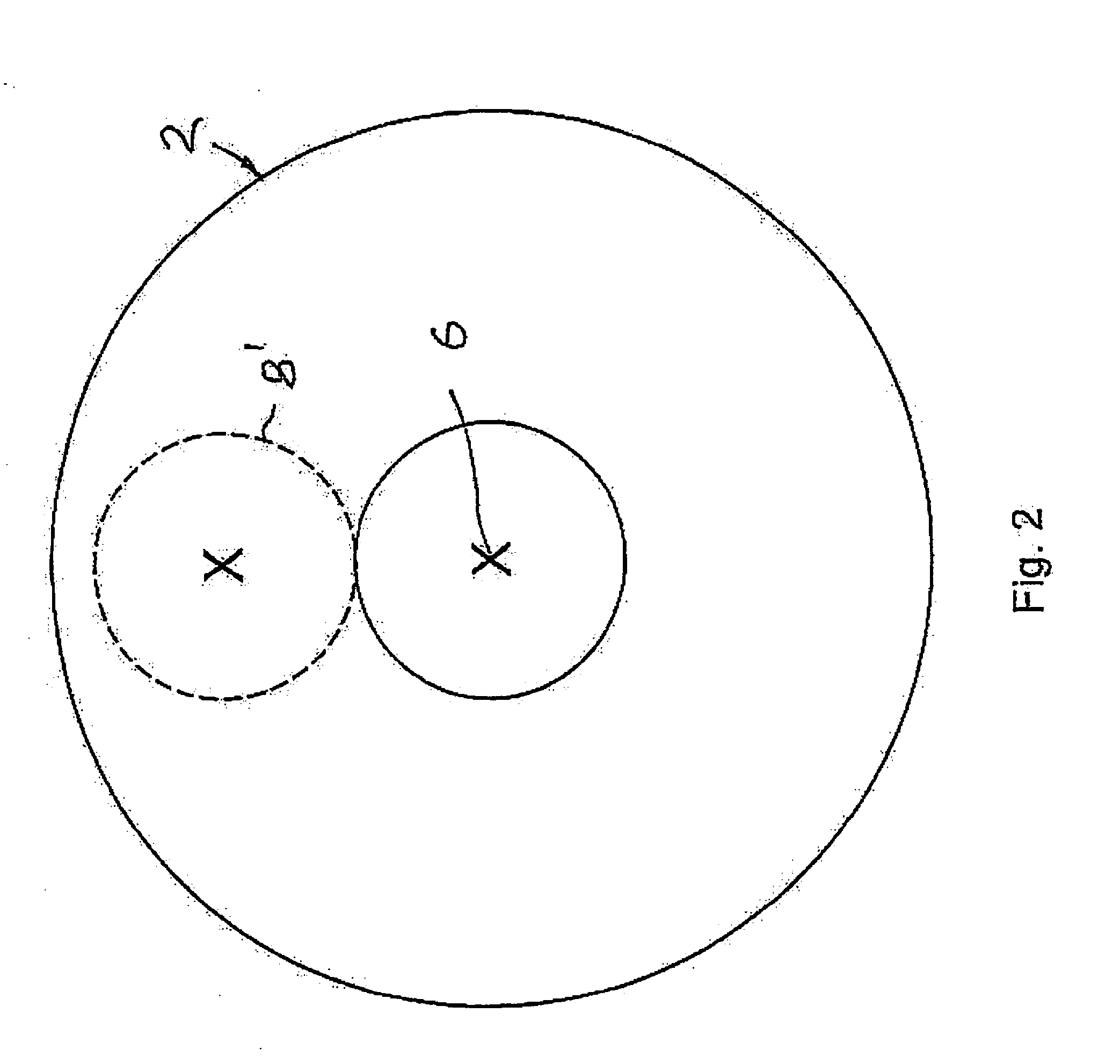
[0038]It is apparent from FIG. 2, which shows a section along a line A-A in FIG. 1, that the crank bearing 8′ is situated eccentrically with respect to the main bearing 4 and the main axis of rotation 6. The same applies for the crank bearing 8.
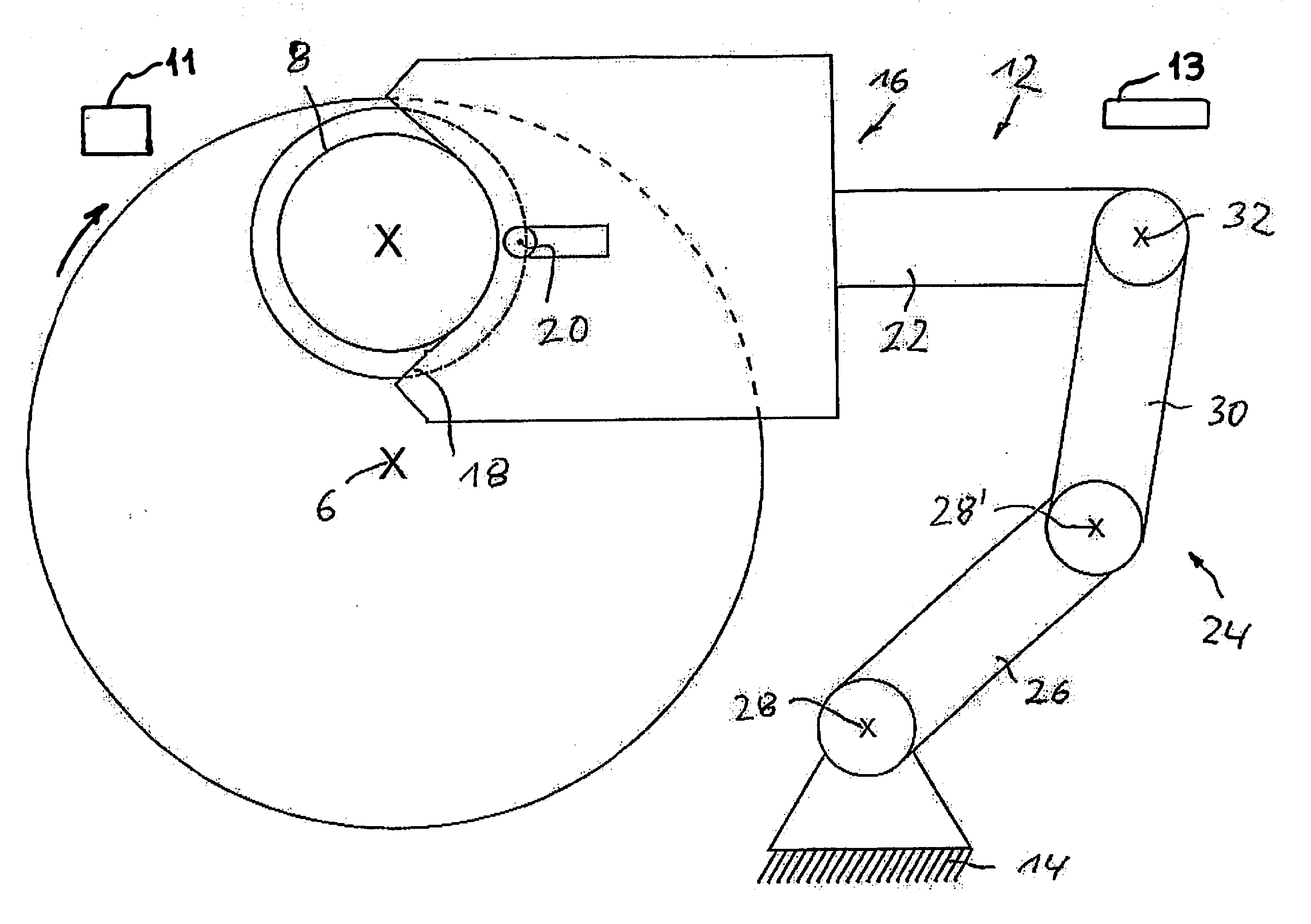
[0039]FIG. 3 shows, in enlarged scale, a detail from FIG. 1 in the area of the crank bearing 8, illustrating the geometry of the crank bearing 8 in greater detail. The crank bearing 8 has o...
PUM
 Abstract
Description
Claims
Application Information
 - R&D
- Intellectual Property
- Life Sciences
- Materials
- Tech Scout
- Unparalleled Data Quality
- Higher Quality Content
- 60% Fewer Hallucinations
Browse by: Latest US Patents, China's latest patents, Technical Efficacy Thesaurus, Application Domain, Technology Topic, Popular Technical Reports.
© 2025 PatSnap. All rights reserved.Legal|Privacy policy|Modern Slavery Act Transparency Statement|Sitemap|About US| Contact US: help@patsnap.com


