
Touch-sensing electrode structure and touch-sensitive device

a technology of touch sensing electrodes and electrodes, applied in the direction of instruments, computing, electric digital data processing, etc., can solve the problems of poor linearity, inability to accurately detect touch positions, inferior linearity, etc., to achieve improved linearity, large capacitive coupling area, and high positional accuracy

Inactive Publication Date: 2017-06-20
WINTEK CORP
View PDF24 Cites 4 Cited by
  • Summary
  • Abstract
  • Description
  • Claims
  • Application Information

AI Technical Summary

Benefits of technology

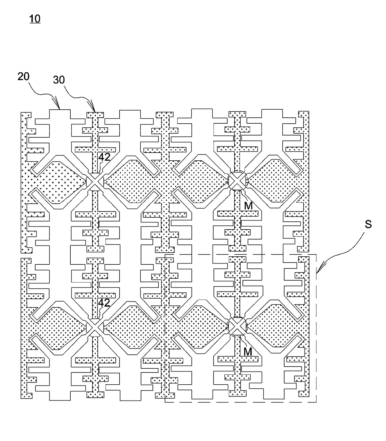
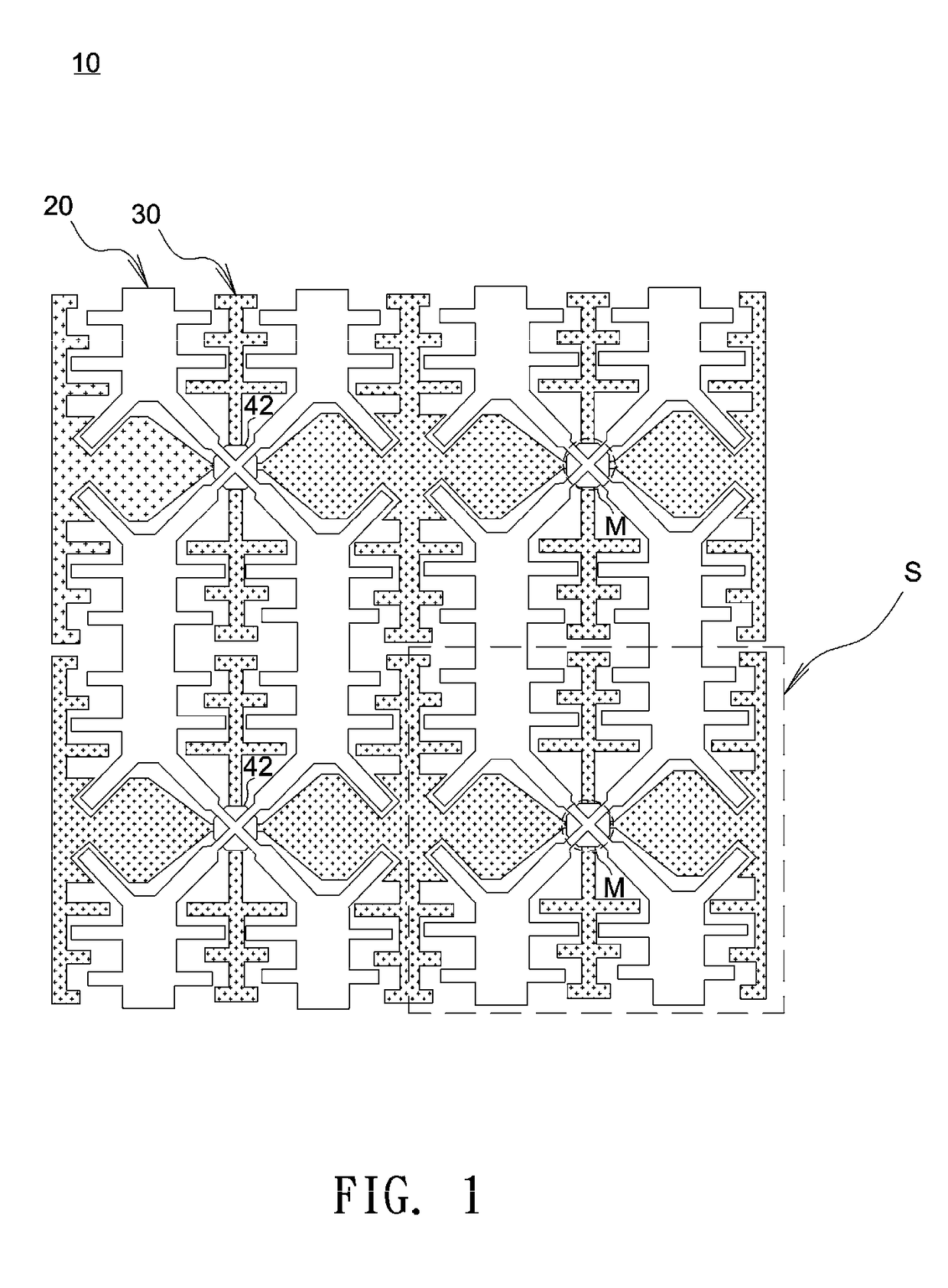
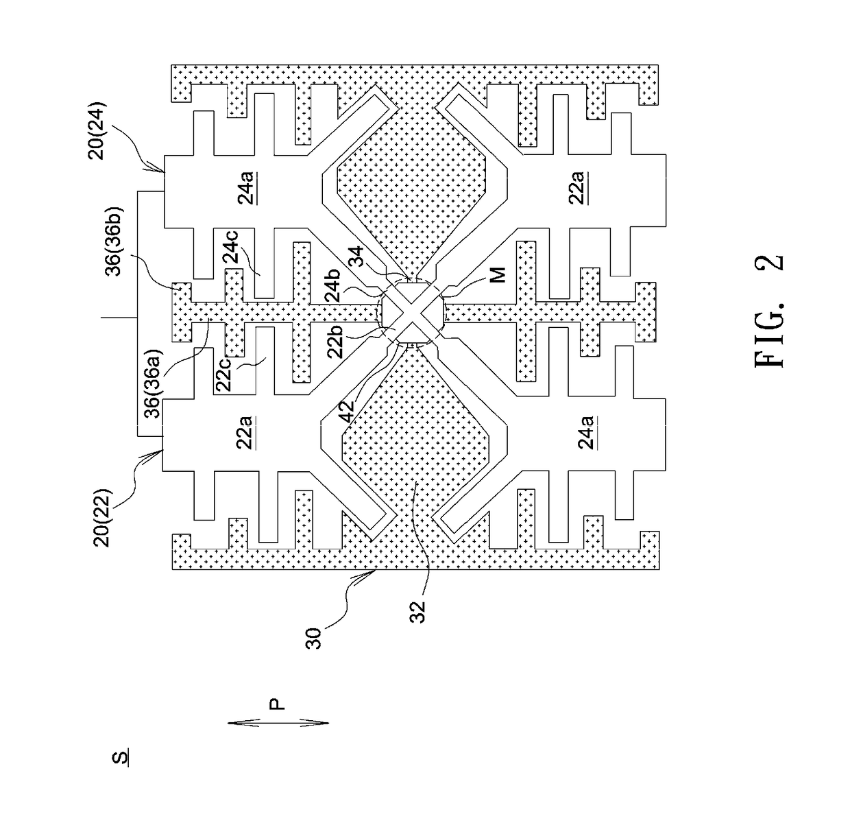
The invention provides a touch-sensing electrode structure and a touch-sensitive device with large capacitive coupling areas, high positional accuracy, and improved linearity. The first electrode has two major parts intersected with each other to form at least one interconnect section, and the second electrode crosses over the interconnect section in a crosswise manner. This increases the effective capacitive coupling area at or around the interconnect section. Additionally, the second electrode has branches that alternate with branches of the first electrode, which further enhances the fringe electric field and increases the amount of mutual capacitance. The lengths of branches can be optimized to further increase linearity and positional accuracy.

Problems solved by technology

However, as shown in FIG. 9, when a small object 106 touches the center of a transparent electrode D, the IC is unable to detect the variations in the fringe mutual capacitance formed between the transparent electrode D and neighboring transparent electrodes and thus fails to accurately detect touch positions.
Therefore, a typical capacitive touch panel fails to achieve accurate positioning unless the touch object is large enough to provide sufficient contact areas.
This may result in inferior linearity and inaccurate positioning, particular when a touch object slides across an interface between the first electrode 102a and the second electrode 102b.

Method used


Image

  • Touch-sensing electrode structure and touch-sensitive device
  • Touch-sensing electrode structure and touch-sensitive device
  • Touch-sensing electrode structure and touch-sensitive device

Examples


Embodiment Construction

[0030]In the following detailed description of the preferred embodiments, reference is made to the accompanying drawings which form a part hereof, and in which are shown by way of illustration specific embodiments in which the invention may be practiced. In this regard, directional terminology, such as “top,”“bottom,”“front,”“back,” etc., is used with reference to the orientation of the Figure(s) being described. The components of the invention can be positioned in a number of different orientations. As such, the directional terminology is used for purposes of illustration and is in no way limiting. On the other hand, the drawings are only schematic and the sizes of components may be exaggerated for clarity. It is to be understood that other embodiments may be utilized and structural changes may be made without departing from the scope of the invention. Also, it is to be understood that the phraseology and terminology used herein are for the purpose of description and should not be ...


PUM


Abstract

A touch-sensing electrode structure includes multiple first electrodes and multiple second electrodes. Each of the first electrodes includes at least a first major part and a second major part, the first major part and the second major part cross over each other to form at least one interconnect section, the interconnect section includes a first connecting line extending in a first direction and a second connecting line extending in a second direction different to the first direction. Each of the second electrodes includes a plurality of electrode sections and third connecting lines, each of the third connecting lines is connected between two adjacent electrode sections, the third connecting lines extend in a third direction different to the first direction and the second direction, and at least one of the third connecting lines overlaps the interconnect section.

Description

BACKGROUND OF THE INVENTION[0001]a. Field of the Invention[0002]The invention relates to a touch-sensing electrode structure and a touch-sensitive device.[0003]b. Description of the Related Art[0004]FIG. 9 shows a schematic diagram of a conventional touch-sensing electrode structure. As shown in FIG. 9, a touch-sensing electrode structure 100 includes multiple first sensing series 102 and multiple second sensing series 104. Each first sensing series 102 includes multiple first electrodes 102a connected with each other by multiple first connecting lines 102b, each second sensing series 104 includes multiple second electrodes 104a connected with each other by multiple second connecting lines 104b, and an insulation layer (not shown) is disposed between the first connecting lines 102b and the second connecting lines 104b. When a finger or a conductor approaches the touch-sensing electrode structure 100, the finger or the conductor may attract some of fringing electric field lines betwe...

Claims


Application Information

Patent Timeline
Patent Type & Authority Patents(United States)
IPC IPC(8): G06F3/044
CPCG06F3/044G06F3/0443G06F3/0446G06F3/0448
Inventor LU, CHIA-CHINGSU, KUO-CHANGJU, TAISU, CHEN-HAOCHEN, YU-TING
Owner WINTEK CORP
Learn More