Base for an orthodontic appliance

a technology for orthodontic appliances and bases, applied in the direction of brackets, arch wires, etc., can solve the problems that metal appliances generally have limited chemical bonding, and achieve the effects of convenient manufacturing, easy retraction, and convenient manufacturing

Active Publication Date: 2017-06-27
ORTHODONTIC RES & DEV
View PDF38 Cites 2 Cited by
  • Summary
  • Abstract
  • Description
  • Claims
  • Application Information

AI Technical Summary

Benefits of technology

[0010]In this aspect, an orthodontic appliance is provided that due to the shape of the protrusions provides mechanical retention once attached to the teeth in three directions. Firstly due to the arrangement of various protrusions extending in a first direction (e.g. up-down) next to each other, mechanical retention is provided in the mesial-distal direction. Due to the shape of the protrusions, mechanical retention may be provided both in the lingual-labial direction and the mandible-maxilla direction (i.e. up-down). Furthermore, due to the distance between the protrusions being at least as large at the edges than at a more central portion, the appliance may be easily manufactured using e.g. injection moulding or micro-injection moulding. However, it should be noted that embodiments of the present invention may also be manufactured using machining techniques such as e.g. milling.
[0013]In some embodiments, one or more of the protrusions along its length has a linearly varying cross-section in planes substantially perpendicular to said first direction. In particular, the width may vary linearly along the length of the protrusion. These embodiments may be relatively easily manufactured. Alternatively, one or more of the protrusions along its length has a non-linearly varying cross-section in planes substantially perpendicular to said first direction.
[0014]In some embodiments, said protrusions have the widest cross-section in planes substantially perpendicular to said first direction substantially midway between said first and said second edge. In these cases, two negative moulds may be used for manufacturing. The split between these moulds may be substantially midway between the first and second edge. In alternative embodiments, the split between two negative moulds does not need to be midway between the first and second edge. If the distance between the protrusions is substantially larger at the edges than at a central portion, the moulds may be easily retracted after moulding.
[0015]In some embodiments, one or more of said protrusions have a dovetail cross-section in planes substantially perpendicular to said first direction. The dovetail cross-section is well known in the field, may be easily manufactured and provides good mechanical retention. In some other embodiments, one or more of said protrusions have a bulged cross-section in planes substantially perpendicular to said first direction. In yet other embodiments, the protrusions may comprise locally increased widths at one or more heights.
[0016]In some embodiments, the orthodontic appliance may be metallic. However, in other embodiments, polymers may be used. For example, the use of e.g. polysulfones is well known in the field. In yet further embodiments, ceramics may be used or fibre-reinforced composites. Regardless of the material used, the shape and arrangement of the protrusions may ensure sufficient bonding to the teeth.

Problems solved by technology

For example, metallic appliances generally have limited chemical bonding.

Method used


Image

  • Base for an orthodontic appliance
  • Base for an orthodontic appliance
  • Base for an orthodontic appliance

Examples


Embodiment Construction

[0030]FIG. 5 shows schematically the arrangement of teeth in the lower jaw (mandible). A front portion of the mouth 110 may be referred to as a mesial region. A rear portion of the mouth 120 may be referred to as a distal region. An inner portion of the mouth behind the teeth 130 may be referred to as a lingual region. An outer portion of the mouth 140 may be referred to as a labial region. A mesial-distal direction 115 with respect to a specific tooth (first molar) has been schematically indicated in FIG. 5. Also indicated in FIG. 5 is a lingual-labial direction 135 with respect to the same tooth. This terminology will be adhered to in the present disclosure.

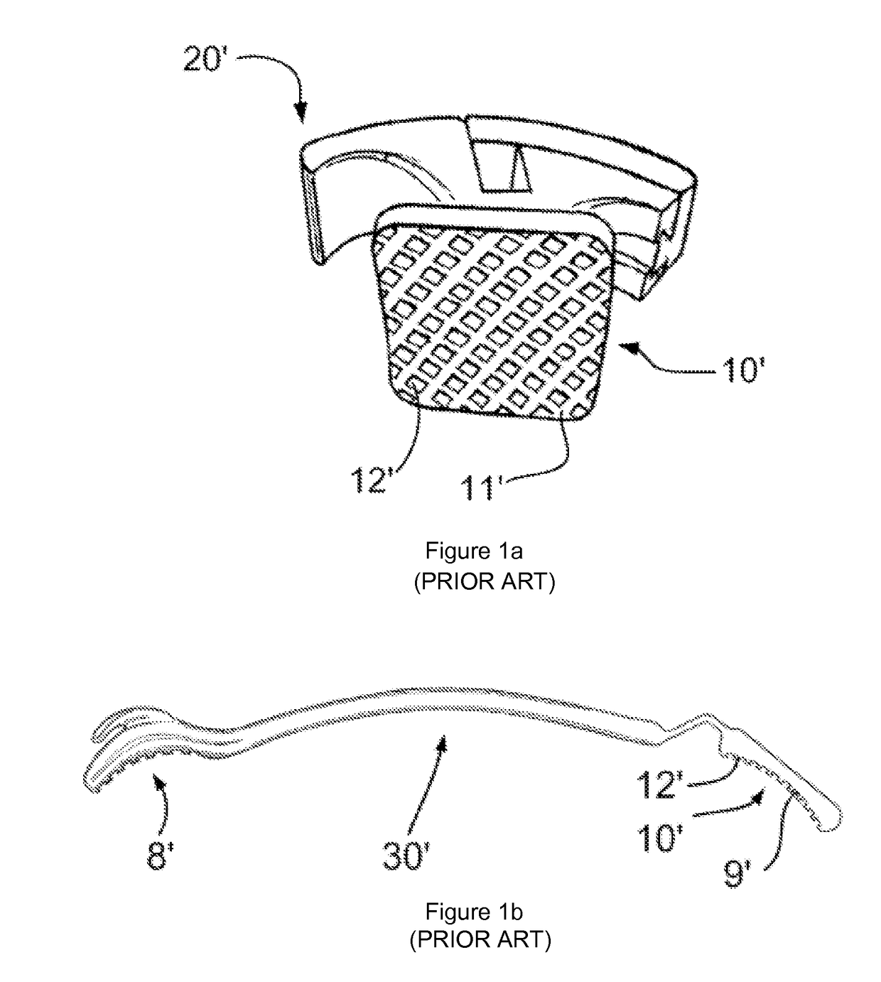
[0031]FIG. 1a illustrates a prior art bracket 20′ having a base 10′. The base may be integrally manufactured with the bracket or may be separately manufactured and subsequently attached to the main body of the bracket. The base 10′ comprises a base surface 11′ which may be slightly concave and may be adapted to fit on a specifi...


PUM


Abstract

Base for an orthodontic appliance includes a base surface adapted to be attached to a tooth and a plurality of protrusions protruding from the base surface and extending along a first direction substantially from a first edge of the base surface to a second edge of the base surface, a second direction being defined as perpendicular to the base surface, wherein the distance between two of the protrusions in a plane substantially perpendicular to the first direction along at least a portion of the protrusions is smaller than the distance between the two protrusions at the base surface, and wherein the distance between two of the protrusions in planes substantially perpendicular to the second direction at the first edge and the second edge is larger than a distance between the two protrusions in a plane between the first and the second edge.

Description

[0001]This application claims the benefit of European Patent Application EP11382340.5 filed on 8 Nov. 2011, which is hereby incorporated in its entirety by reference.[0002]The present invention relates to a base for an orthodontic appliance. It further relates to an orthodontic appliance comprising such a base.BACKGROUND ART[0003]Many different orthodontic appliances are known to correct malocclusions, such as e.g. crowns, bridges, brackets, distalizers and retainers. Some of these appliances may in use be attached to the surface of a tooth or various teeth in order to correct the orientation or position of one or more teeth. Depending on their function they may be attached on the lingual or labial surface of an incisor, canine, premolar or molar.[0004]Examples of orthodontic appliances that may be attached to teeth include of course the well known brackets, but also e.g. distalizers such as known from e.g. US 2006 / 018833, and also e.g. buccal tubes, molar tubes, lingual buttons and...

Claims


Application Information

Patent Timeline
Patent Type & Authority Patents(United States)
IPC IPC(8): A61C7/28A61C7/16A61C7/14
CPCA61C7/282A61C7/14A61C7/16
Inventor CARRIERE LLUCH, LUISCARRIERE PONS, JOSE
Owner ORTHODONTIC RES & DEV
Why Eureka
Try Eureka