Electric connector

a technology of electric connectors and threads, applied in the direction of electrical equipment, contact members penetrating/cutting insulation/cable strands, coupling device connections, etc., can solve the problems of high cost of electric connectors, time-consuming and labor-intensive threads provided for locking and crimping, and requiring tools for operation, so as to ensure product stability

Active Publication Date: 2017-06-27
KUNSHAN AMPHENOL ZHENGRI ELECTRONICS +1
View PDF5 Cites 5 Cited by
  • Summary
  • Abstract
  • Description
  • Claims
  • Application Information

AI Technical Summary

Benefits of technology

[0008]Wherein, when each U-shaped insert is passed and coupled to each pocket, spacing exists between the two second inclined surfaces of each pair of U-shaped rods. Since the spacing adjacent to the first connector seat is greater than the width of the U-shaped insert, so that when the U-shaped insert cuts into the insulating layer, the insert has not been stopped by the second inclined surface, and the electric connector is capable of controlling the width between the two blades of the U-shaped insert and controlling the amount of deformation of the two blades.
[0009]Wherein, whe

Problems solved by technology

However, the aforementioned electric connector has the following drawbacks: The pin b2 is connected to the cable mainly by soldering, and the thread provided for locking and crimping takes much time and effort and requires tools for operation, and such electric connector is just applicable for connecting

Method used


Image

  • Electric connector
  • Electric connector
  • Electric connector

Examples


Embodiment Construction

[0019]The technical contents of the present invention will become apparent with the detailed description of preferred embodiments accompanied with the illustration of related drawings as follows. It is noteworthy that the preferred embodiments are provided for illustrating this disclosure rather than restricting the scope of the disclosure.

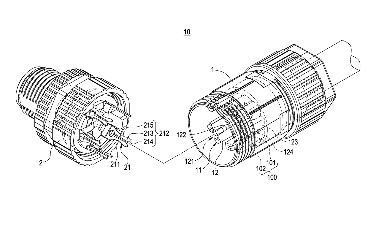
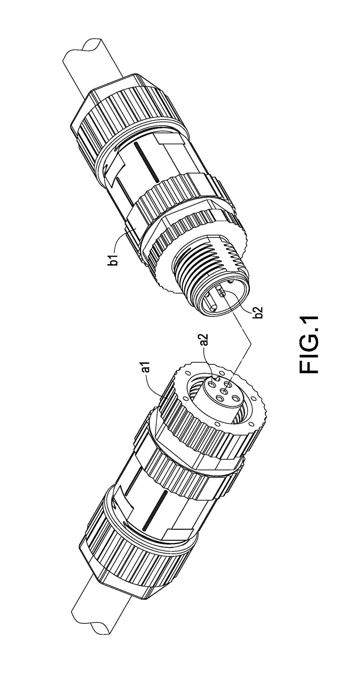
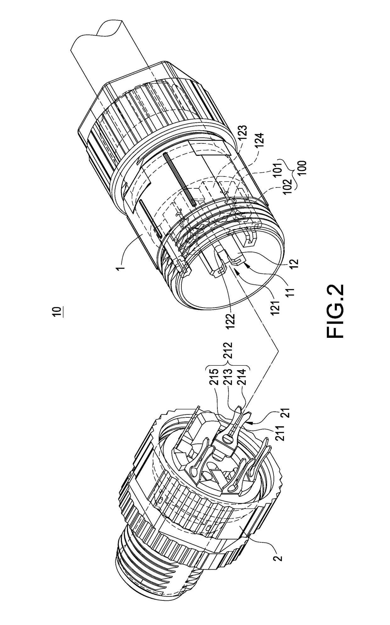
[0020]With reference to FIGS. 2 to 9 for an electric connector of this disclosure, the electric connector is used for a plurality of first cables 100 and a plurality of second cables, and each first cable 100 has a core wire 101 and an insulating layer 102, and the electric connector 10 comprises a first connector seat 1 and a second connector seat 2.

[0021]In FIGS. 2, and 4 to 9, the first cables 100 are passed and coupled to the first connector seat 1, and the first connector seat 1 has a plurality of cable clamps 11, and each cable clamp 11 includes a pair of U-shaped rods 12 extended from the first connector seat 1, and each pair of U-shaped ro...


PUM


Abstract

An electric connector (10) includes a first connector seat (1) and a second connector seat (2). The first connector seat (1) has plural cable clamps (11), and each cable clamp (11) includes a pair of U-shaped rods (12). Each pair of U-shaped rods (12) has a pocket (121), two inner sides (122), and two outer sides (123). The two inner sides (122) have plural cable fixing slots (124), and the cable fixing slots (124) have a slot width (h) tapered towards the first connector seat (1). The second connector seat (2) has plural pins (21), and each pin (21) is passed and coupled to each pocket (121).

Description

FIELD OF THE INVENTION[0001]This disclosure relates to an electric connector, and more particularly to an electric connector for outputting, inputting, or transmitting electric power or electric signals.BACKGROUND OF THE INVENTION[0002]With reference to FIG. 1 for a conventional electric connector, the electric connector comprises a first joint cylinder a1, a second joint cylinder b1, a plurality of first cables, and a plurality of second cables, and the first joint cylinder a1 has a plurality of jacks a2, and the core wire in each first cable is soldered and connected, and a thread is provided for locking and crimping to connect the cables and pins to each jack a2, and the second joint cylinder b1 has a plurality of pins b2, and each pin b2 is soldered and connected, and a thread is provided for locking and crimping to electrically connect each second cable. Wherein, the first joint cylinder a1 and the second joint cylinder b1 are connected with each other, and each first cable is ...

Claims


Application Information

Patent Timeline
IPC IPC(8): H01R4/38H01R13/512H01R4/24
CPCH01R4/2433H01R13/512
Inventor HUNG, JEN-YUAN
Owner KUNSHAN AMPHENOL ZHENGRI ELECTRONICS
Why Eureka
Try Eureka