Filling head of low vacuum filling machine

A filling machine and filling head technology, applied in the fields of food machinery and pharmaceutical machinery, can solve problems affecting product quality, filling speed and filling accuracy, and filling volume, so as to ensure quality and production stability , Guaranteed accuracy and production speed, and a wide range of applications

Inactive Publication Date: 2015-12-30
长沙铭盛科技发展有限公司
View PDF8 Cites 1 Cited by
  • Summary
  • Abstract
  • Description
  • Claims
  • Application Information

AI Technical Summary

Problems solved by technology

[0003] In the first structure, since the liquid outlet of the filling tube is around the vacuum tube, the liquid medicine is easy to flow to the middle during filling, and the liquid medicine in the middle is sucked away by the vacuum, and the vacuum tube is easily blocked. , thus affecting the filling speed and filling accuracy
The second structure adds a liquid-separating umbrella to separate the liquid, which will have the following problems: 1. During filling, most of the liquid through the liquid-separating umbrella can be poured into the bottle, but a small part of the liquid is still pumped away. Affect the filling speed, also affect the filling volume
2. Due to the liquid separation umbrella, the outer diameter of the filling part inserted into the bottle increases, so this structure is not suitable for filling bottles with a small bottle mouth; at the same time, for bottles with a large bottle mouth, the filling Neutralization is more difficult. If there is a slight deviation, the liquid separator may hit the bottle wall, producing particles, damaging the filling head, and affecting product quality.
However, this patent does not solve the above-mentioned problem in the filling process of the back suction process, and the neutral problem, etc.

Method used


Image

  • Filling head of low vacuum filling machine

Examples


Embodiment

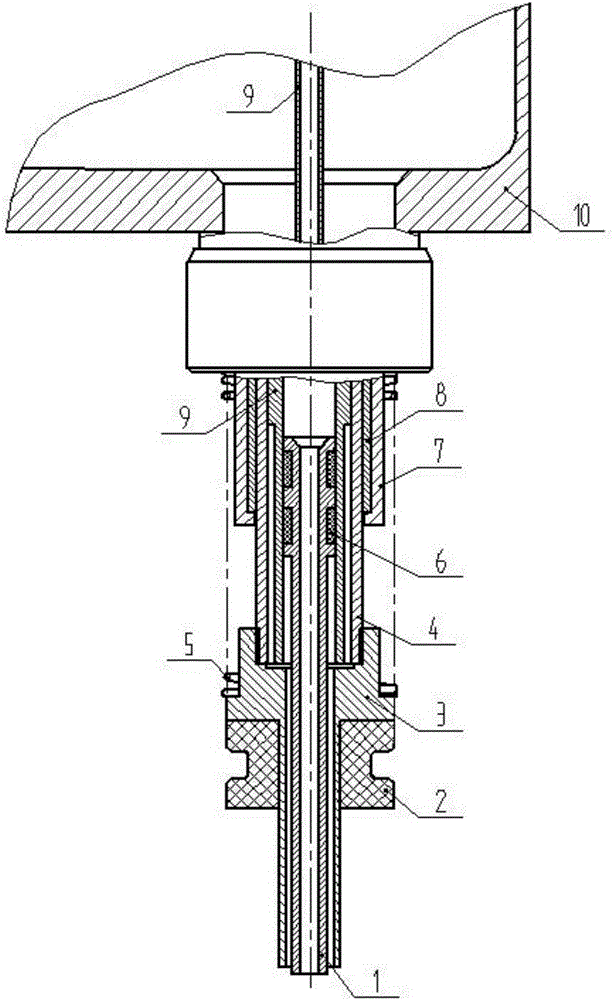
[0023] Such as figure 1 As shown, the filling head of a negative pressure filling machine provided by the present invention includes a filling tube 1, a bottle mouth gasket 2, a vacuum tube 3, a valve core 4, a coupling nut 7, a guide sleeve 8, and a ventilation tube 9 , spring 5 and guide sealing ring 6, the upper end of the vacuum pumping tube 3 is connected with the lower end of the valve core 4, the vent pipe 9 is sleeved on the inner wall of the valve core 4, and the outer wall of the valve core 4 is sleeved The guide sleeve 8, the outer wall of the guide sleeve 8 is sleeved with the coupling nut 7, the outer wall of the vacuum tube 3 is sleeved with the bottle mouth seal 2, and the upper end surface of the bottle mouth seal 2 withstands the The step surface of the vacuum tube 3; the filling tube 1 is penetrated on the inner wall of the vacuum tube 3 and the vent tube 9, the outer wall of the upper end is matched with the inner wall of the vent tube 9, and the groove of t...


PUM


Abstract

The invention discloses a filling head of a low vacuum filling machine. The filling head of the low vacuum filling machine comprises a filling pipe, a bottle opening sealing pad, a vacuumizing pipe, a valve core, a connection nut, a guide sleeve, a ventilation pipe, a spring and a guide sealing ring, wherein the upper end of the vacuumizing pipe is connected with the lower end of the valve core; the inner wall of the valve core is sleeved by the ventilation pipe; the outer wall of the valve core is sleeved by the guide sleeve; the outer wall of the guide sleeve is sleeved by the connection nut; the outer wall of the vacuumizing pipe is sleeved by the bottle opening sealing pad; the filling pipe penetrate through the inner walls of the vacuumizing pipe and the ventilation pipe; the spring is mounted on the outer wall of the upper end of the vacuumizing pipe; the spring is mount in a manner of extending to the outer wall of the connection nut; a liquid outlet in the lower end of the filling pipe protrudes from an air extraction opening in the lower end of the vacuumizing pipe. According to the filling head of the low vacuum filling machine, the phenomenon that the liquid is pumped out during filling is avoided; the filling part is small in size of the outer diameter; the centering difficulty is reduced; the production speed and the product quality are improved; the production cost is reduced.

Description

technical field [0001] The invention belongs to the technical field of pharmaceutical machinery and food machinery, and in particular relates to a filling head of a negative pressure filling machine. Background technique [0002] In the prior art, the filling head of the negative pressure filling machine mainly has the following two structural forms: one is that the vacuum tube and the filling tube in the filling head are welded together to form a sleeve, and the vacuum tube and the filling tube are welded together. The bottom of the tube is basically flush and welded together, the inner tube at the bottom is evacuated, and the outer casing drills several holes in the bottom for filling and discharging the filling liquid. The 2nd, the evacuation tube and the filling tube in the filling head are also nested together, but the evacuation tube stretches out a part more than the filling tube, in order to avoid liquid, add a liquid-dispensing umbrella on its filling tube. There a...

Claims


Application Information

Patent Timeline
IPC IPC(8): B67C3/26
Inventor 毛小德
Owner 长沙铭盛科技发展有限公司
Why Eureka
Try Eureka