Reconfigurable power control system

a power control system and reconfigurable technology, applied in the integration of power network operation systems, transmission systems, circuit arrangements, etc., can solve the problems of reducing the overall reliability of led bulbs, driving up costs, and reducing the overall efficiency of led lighting systems

Active Publication Date: 2017-06-27
IVANI
View PDF55 Cites 30 Cited by
  • Summary
  • Abstract
  • Description
  • Claims
  • Application Information

AI Technical Summary

Problems solved by technology

This drives up cost as the electronics must be mounted on each bulb, and are discarded when the bulb is replaced.
It also decreases overall reliability of the LED bulb because it provides for a larger number of electronic components that can fail (LEDs are inherently 40 times more reliable than incandescent filaments, but LED bulbs generally do not show the same multiplier of reliability).
Further, individual control electronics also reduce the overall efficiency of the LED lighting system as the AC power has to be converted into DC power at a variety of points resulting in creation of waste heat.
Still further, the heat generated from this conversion can be problematic.
Certain LED bulbs can only be installed in certain orientations without presenting possible fire hazards, and, even if heat can be controlled, the creation of waste heat within the LED bulb structure can result in further reliability issues due to potential damage.
Thus, while the use of retrofit LED lighting has dramatically reduced power consumption in structures which use them consistently, it is clear that they still operate very inefficiently, and cost much more, than their inherent capability.
It is generally difficult to cause severe damage to the human body with DC power because it has little effect on human electromechanics.
While this can be an effective solution, it is far from efficient as even while LEDs can run for many years off of batteries, this arrangement produces a large amount of battery waste and many direct generation sources are only useable in certain circumstances.
However, such a solution has generally not been possible with current lighting systems or structures.
The cost of wiring (independent of the actual fixture costs) in a new structure generally has two components, first the cost of the wire itself, and second, the cost of the labor to install it.
In these types of arrangements, the two-way, three-way and higher way arrangement of switches (where the same fixture can be controlled from multiple switches) requires significantly more labor time from more experienced electricians, specialized components, and more wire to interconnect the operation.
In effect, if a system is wired simply where the wires connect directly to the outlet from both switches, one has to turn both switches off to turn the outlet off, while any one of them being on will result in power.
This does not allow for free toggling.
This complication therefore costs significantly extra to install both in parts (due to the more complicated switches and additional wiring) and labor (to make sure they are connected correctly).
The cause of this complication is that the operation of the switch is physically connected to the functionality of the switch.
Because each wire leading into an outlet is either on or off, it can be impossible to provide for the ability to freely toggle power from any of the switches without adding additional paths which reconnect the flow in different ways.
One major problem in all electrical wiring systems is that once an electrician has wired the system during construction (which usually occurs when only the skeleton of the structure exists and it is easy to construct things that will eventually be within walls), the only way to change the system is a physical rewiring of the system.
This is usually very costly as it can require tearing the surfaces (usually drywall) off of walls to access the wires, or it requires sophisticated tools to thread new wires through difficult to access (and even to see) passageways.

Method used


Image

  • Reconfigurable power control system
  • Reconfigurable power control system
  • Reconfigurable power control system

Examples


Embodiment Construction

)

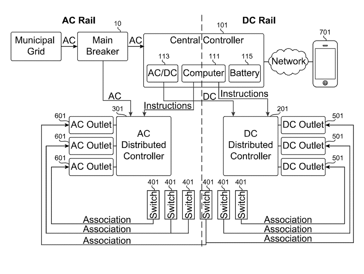
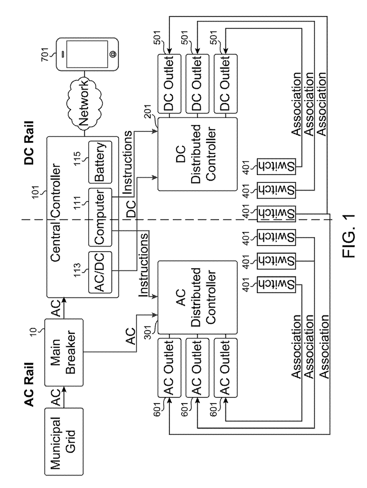
[0036]A house or other structure used by humans will traditionally have a power distribution system arranged within it. In common parlance, this is usually referred to as the structures “wiring” as wires will extend from a central main breaker to distribute power which is obtained by the main breaker from an external power grid to a variety of outlets through the structure. In this disclosure, the distribution systems will be referred to as “rails”. This is a term commonly used in computer circuit design to refer to the primary source of power on a circuit board but is not commonly used in housing. This term is used herein as it provides for a clearer term more connected with the idea that the rail is the infrastructure portion of the wiring in the structure.

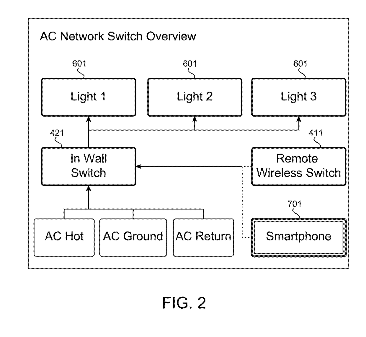
[0037]Similarly, this disclosure will refer to power “outlets”. In general parlance, a power outlet is generally a point of connection which allows for devices which can be completely external to the power rail to be connected ...


PUM


Abstract

Systems and methods for the creation of a centrally controlled DC and AC power rail system within a structure. The rails utilize a centralized controller along with a plurality of distributed controllers to allow for power in the rails to be selectively distributed or not distributed to outlets attached to the rails. This allows for power to be distributed without the need for users to utilize hardwired switches, but to instead utilize generally wireless switch modules, which may be implemented in hardware and / or software to control the outlets. It also allows for devices designed to utilize DC power to be directly supplied with such power from the DC power rail without the need to include onboard AC-DC converters with each device.

Description

CROSS REFERENCE TO RELATED APPLICATION(S)[0001]This application claims benefit of U.S. Provisional Patent Application Ser. No. 61 / 932,085, filed Jan. 27, 2014, the entire disclosure of which is herein incorporated by reference.BACKGROUND[0002]1. Field of the Invention[0003]This disclosure is related to a controller for a power system within a structure such as a residence or business. Specifically, the control system generally serves to provide centralized control of power distribution on both AC and DC circuits wired into the structure.[0004]2. Description of the Related Art[0005]Today there is an increasing emphasis on energy efficiency, not only for the individual and the company, who are the energy consumers, but also for energy providers. This is especially true for electrical energy. The Energy Information Administration (EIA) estimates that in 2011 about 461 Billion kW hours of electricity were used in the USA by the residential and commercial sectors. Electricity used for li...

Claims


Application Information

Patent Timeline
Patent Type & Authority Patents(United States)
IPC IPC(8): H02J5/00H05B37/02H05B44/00
CPCH02J5/00H05B37/0272Y10T307/367Y04S20/246H02J3/10H05B47/19H02J13/00024H02J13/00026Y02B70/30H02J13/00022
Inventor WOOTTON, MATTHEWWOOTTON, JOHNMCKINNEY, JUSTINKING, JR., LLOYD HERBERT
Owner IVANI
Why Eureka
Try Eureka